INS_CNGE2+2SMS_REV– 02/19/13 PAGE 14
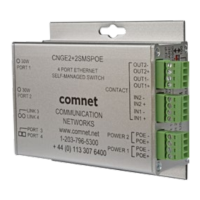
INSTALLATION AND OPERATION MANUAL CNGE2+2SMS[POE][HO]
TECH SUPPORT: 1.888.678.9427
DIP Switches
The CNGE2+2SMS’s dip switches configure switch features. The DIP Switches are numbered from
left to right when viewing the side of the Switch with the backplate on the bottom and the power
connections on the left. If “Web Management Enable” is selected in the management software
under System Settings, the DIP switch settings will be overridden by any settings made in the
browser interface.
DIP Switch
Position Description
1 RSTP enable (down = disabled, up enabled)
2 Port SMS Mux
3 Root Bridge Select
4 Redundant SFP mode
5 IGMP enable
6 SFP Port 3 speed. Up: 1000M/Down: 100M
7 SFP Port 4 speed. Up: 1000M/Down: 100M
Switch Function Listing
The switch functions may be set individually or may be combined in the following order to perform
enhanced functions above the individual operation. The table below describes the operation of the
switch functions. This same table is also available in the help menu of the system webpage.
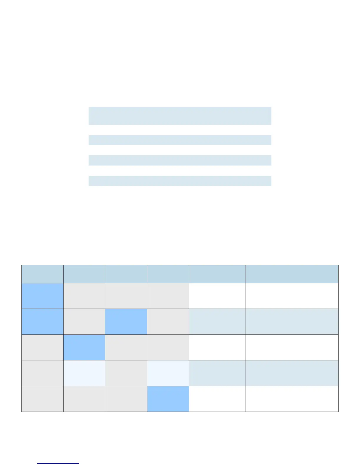
Summary of the switch configurations (in order of switch priority)
RSTP
(Switch 1)
SMS MUX
(Switch 2)
ROOT BR
(Switch 3)
R SFP
(Switch 4)
Resulting Mode Comment
ON OFF OFF OFF RSTP All ring configurations
ON OFF ON OFF RSTP RSTP this bridge set to root
OFF ON OFF OFF SMS
Port4 is uplink (traffic from
ports 1-3 is sent only to port 4)
OFF ON OFF ON
SMS with
Redundant SFP
Fiber fail over
with Port1 and Port2 isolation
OFF OFF OFF ON Redundant SFP
Fiber fail over
Port 4 is primary port