5. ROUTER DESIGN
5.8 Description of the front panel
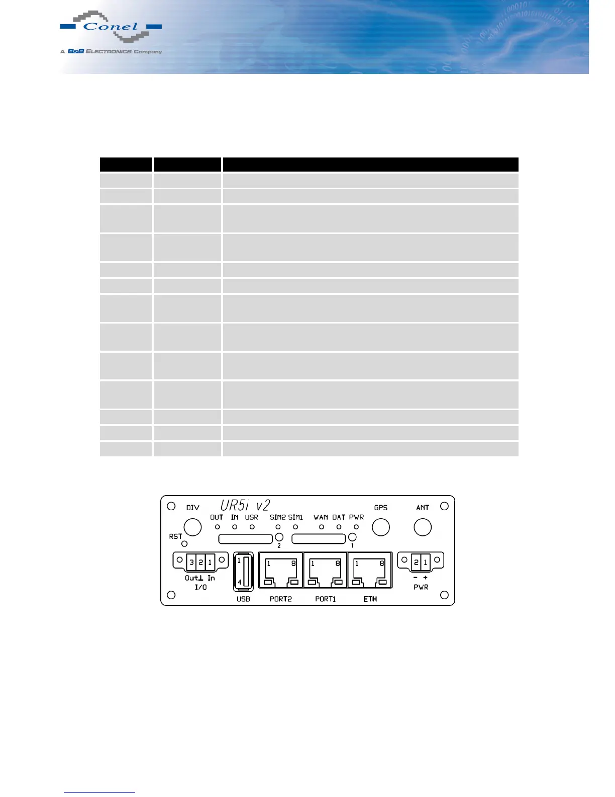
On the front panel is located:
Caption Connector Description
PWR 2-pin Connector for the power supply adapter.
ETH RJ45 Connector for connection into the local computer network.
PORT1 RJ45 Connector for expansion port RS232, RS458/422, MBUS,
ETHERNET, CNT or SWITCH.
PORT2 RJ45 Connector for expansion port RS232, RS485/422, MBUS,
SWITCH, WIFI, WMBUS or SDH (only FULL version).
ANT SMA Connector for main antenna.
DIV SMA Connector for diversity antenna.
GPS SMA Connector for GPS antenna. It can be replaced with connector
for WIFI or WMBUS antenna.
WIFI R-SMA Connector for WIFI antenna. Only when router is equipped
with an expansion por t WIFI.
WMBUS SMA Connector for WMBUS antenna. Only when it is equipped
with an expansion por t WMBUS.
USB USB-A Host Connector for connection of USB devices to the router. Sup-
ports devices with PL-2303 and FTDI USB/RS232 converters.
I/O 3-pin Connector for connection of the binary input and output.
SIM1 — Holder for the first SIM card.
SIM2 — Holder for the second SIM card (only FULL version).
Table 5: Front panel description
Figure 20: Front panel UR5i v2F SL
12