5. ROUTER DESIGN
PORT2 cable plug into the RJ45 connector labeled as PORT1 (see figure below).
Figure 31: PORT2 cable connection
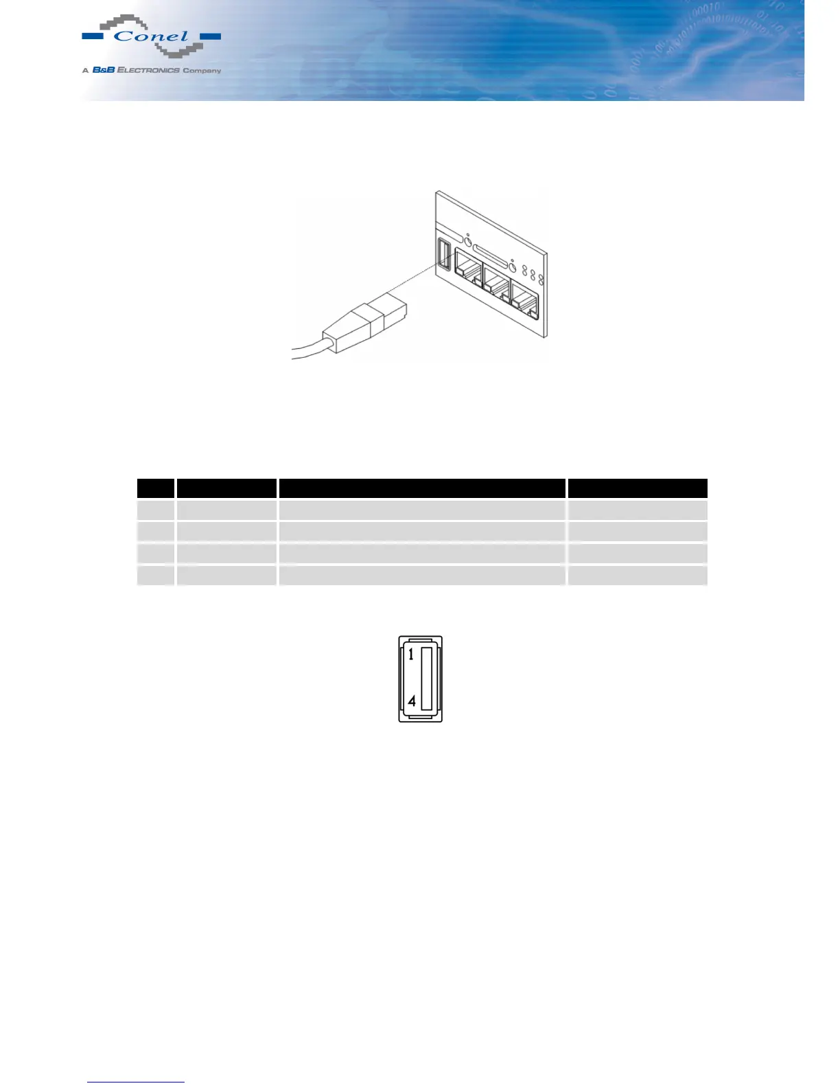
5.8.8 USB Port
Panel socket USB-A.
Pin Signal mark Description Data flow direction
1 +5 V Positive pole of 5 V DC supply voltage
2 USB data - USB data signal – negative pole Input/Output
3 USB data + USB data signal – positive pole Input/Output
4 GND Negative pole of DC supply voltage
Table 9: Connection of USB connector
Figure 32: USB connector
19