5. ROUTER DESIGN
5.8.2 Power connector PWR
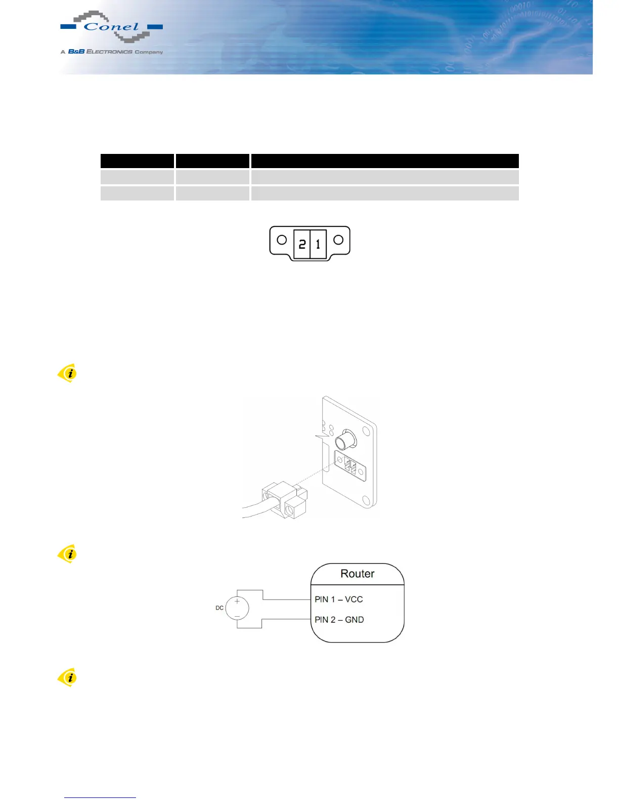
Panel socket 2-pin.
Pin number Signal mark Description
1 VCC(+) Positive pole of DC supply voltage (+10 to +30 V DC)
2 GND(-) Negative pole of DC supply voltage
Table 7: Connection of power connector
Figure 21: Power connector
Power supply for router is required between +10 V to +30 V DC supply. Protection against
reversed polar ity without signaling is built into the router.
The power consumption during receiving is 2,6 W. The peak power consumption during
data sending is 5,5 W. However, values of consumption can be increased, if some expansion
port is eqquipped. For correct operation it is necessary that the power source is able to supply
a peak current of 1 A.
Connector on the power cable connects into the power connector on the router head and
tightens locking screws (see figure below).
Figure 22: Connection of power supply connector
Circuit example:
Figure 23: Connection of power supply
The positive pole VCC is marked by a red socket on the power.
14