53 Commander SE User Guide
www.controltechniques.com Issue Number 8
increases the losses and therefore reduces the amount of regenerated energy
transferring from the motor to the DC Bus for a given deceleration rate. The drive may
extend the deceleration ramp to prevent the drive trippingon overvoltage (OU) if the load
inertia is too high for the programmed deceleration ramp.
For a given amount of energy, mode 2 allows faster deceleration than mode 1, providing
that the motor can withstand the extra losses.
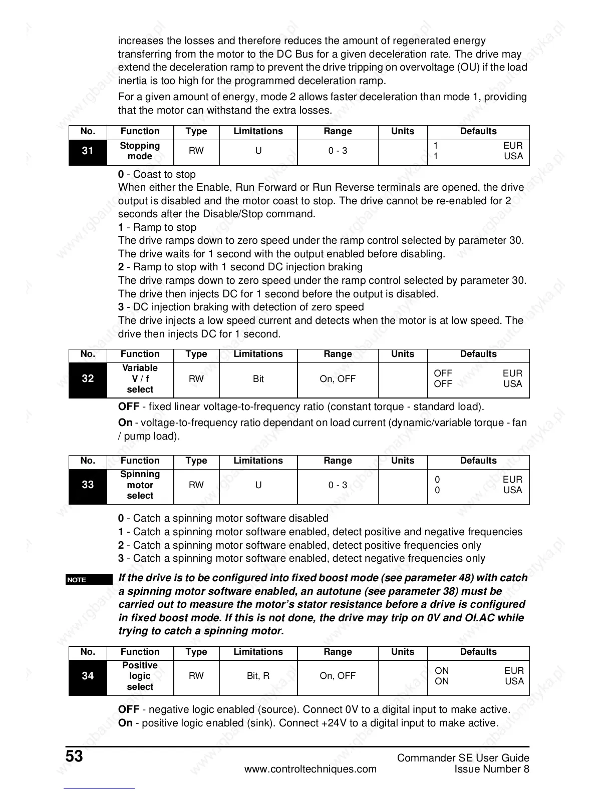
0 -Coasttostop
When either the Enable, Run Forward or Run Reverse terminals are opened, the drive
output is disabled and the motor coast to stop. The drive cannot be re-enabled for 2
seconds after the Disable/Stop command.
1 -Ramptostop
The drive ramps down to zero speed under the ramp control selected by parameter 30.
The drive waits for 1 second with the output enabled before disabling.
2 - Ramp to stop with 1 second DC injection braking
The drive ramps down to zero speed under the ramp control selected by parameter 30.
The drive then injects DC for 1 second before the output is disabled.
3 - DC injection braking with detection of zero speed
The drive injects a low speed current and detects when the motor is at low speed. The
drive then injects DC for 1 second.
OFF - fixed linear voltage-to-frequency ratio (constant torque - standard load).
On - voltage-to-frequency ratio dependant on load current (dynamic/variable torque - fan
/ pump load).
0 - Catch a spinning motor software disabled
1 - Catch a spinning motor software enabled, detect positive and negative frequencies
2 - Catch a spinning motor software enabled, detect positive frequencies only
3 - Catch a spinning motor software enabled, detect negative frequencies only
If the drive is to be configured into fixed boost mode (see parameter 48) with catch
a spinning motor software enabled, an autotune (see parameter 38) must be
carried out to measure the motor’s stator resistance before a drive is configured
in fixed boost mode. If this is not done, the drive may trip on 0V and OI.AC while
trying to catch a spinning motor.
OFF - negative logic enabled (source). Connect 0V to a digital input to make active.
On - positive logic enabled (sink). Connect +24V to a digital input to make active.
No. Function Type Limitations Range Units Defaults
31
Stopping
mode
RW U 0 - 3
1EUR
1USA
No. Function Type Limitations Range Units Defaults
32
Variable
V/f
select
RW Bit On, OFF
OFF EUR
OFF USA
No. Function Type Limitations Range Units Defaults
33
Spinning
motor
select
RW U 0 - 3
0EUR
0USA
NOTE
No. Function Type Limitations Range Units Defaults
34
Positive
logic
select
RW Bit, R On, OFF
ON EUR
ON USA
 Loading...
