32 Commander SK Getting Started Guide
www.controltechniques.com Issue Number: 1
Safety
Information
Rating
Data
Mechanical
Installation
Electrical
Installation
Keypad and
Display
Parameters
Quick Start
Commissioning
Diagnostics Options
Parameter
List
UL Listing
Information
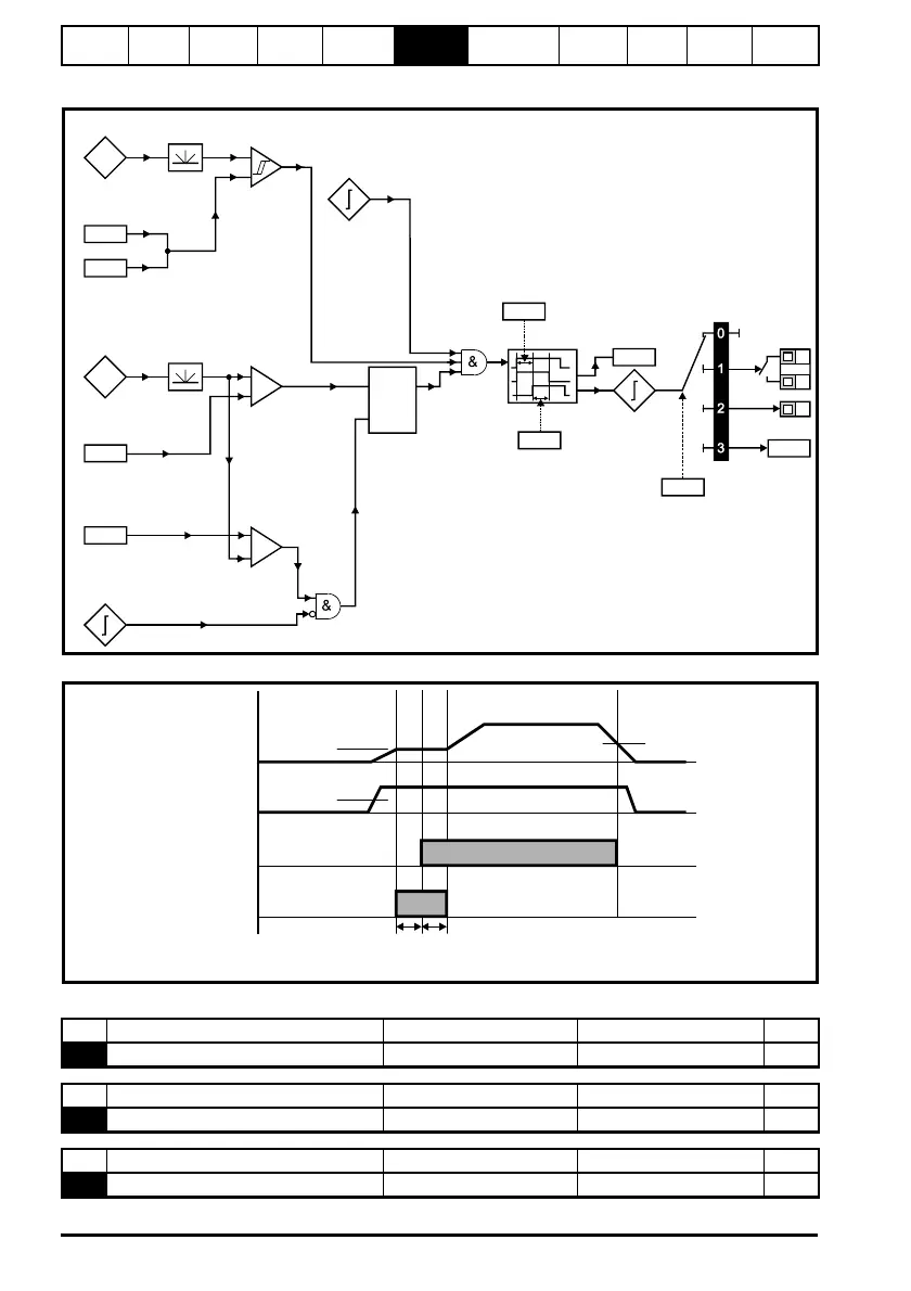
Figure 6-12 Brake function diagram
Figure 6-13 Brake sequence
Pr 52 to Pr 54 appear when a fieldbus option is fitted to the drive.
See the appropriate fieldbus option module manual for further information.
Current
magnitude
Brake release
current threshold
Brake applied
current threshold
46
47
+
_
Output
frequency
Brake release
frequency
Brake apply
frequency
48
49
+
_
+
_
Reference
on
Latch
Drive
active
In
Out
Reset
Pre-brake
release
delay
50
Post brake
release
delay
51
Brake
release
Brake
controller
enable
12
T5
T6
B3
User
programmable
Brake
disabled
Ramp
hold
Pr Brake
release frequency
48:
Pr : Brake release
current threshold
46
Ramp hold
Pr :
Brake applied
frequency
49
Pr :
Pre brake
release dela
50
Pr :
Post brake
release dela
51
Brake release
Output current
Output frequency
No Function Range Defaults Type
52 Fieldbus node address 0 to 255 0 RW
No Function Range Defaults Type
53 Fieldbus baud rate 0 to 8 0 RW
No Function Range Defaults Type
54 Fieldbus diagnostics -128 to +127 0 RW