Commander SK Getting Started Guide 7
Issue Number: 1 www.controltechniques.com
Safety
Information
Rating
Data
Mechanical
Installation
Electrical
Installation
Keypad
and Display
Parameters
Quick Start
Commissioning
Diagnostics Options
Parameter
List
UL Listing
Information
2 Rating Data
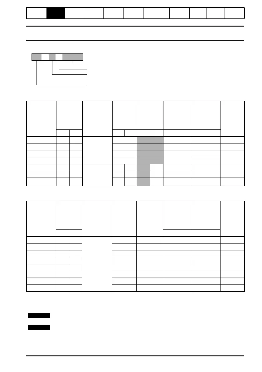
Figure 2-1 Model code explanation
Table 2-1 Commander SK 200V units
Table 2-2 Commander SK 400V units
Output frequency: 0 to 1500Hz
Output voltage: 3 phase, 0 to drive rating (240 or 480Vac maximum set by Pr 08).
SK A 1 2 XXXXX
Drive kilowatt rating: 00025 = 0.25kW
Drive voltage rating: 2 = 230V, 4 = 400V
Number of input phases: 1 = 1phase, 3 = 3phase, D = 1 and 3phase
Frame size
Model: Commander SK
Model
Number
Nominal
motor
power
Supply
voltage and
frequency
Typical
full load
input
current
Maximum
continuous
input
current
100% RMS
output
current
150%
overload
current for
60s
Minimum
braking
resistor
value
Ω
AA A A
kW hp 1ph 3ph 1ph 3ph Heavy Duty
SKA1200025 0.25 0.33
1 phase
200 to
240Vac ±10%
48 to 62Hz
4.3
1.7 2.55 68
SKA1200037 0.37 0.5 5.8
2.2 3.3 68
SKA1200055 0.55 0.75 8.1
3.0 4.5 68
SKA1200075 0.75 1.0 10.5
4.0 6.0 68
SKBD200110 1.1 1.5 1/3 phase
200 to
240Vac ±10%
48 to 62Hz
14.2 6.7
9.2 5.2 7.8 28
SKBD200150 1.5 2.0 17.4 8.7
12.6 7.0 10.5 28
SKCD200220 2.2 3.0 23.2 11.9
17.0 9.6 14.4 28
Model
Number
Nominal
motor
power
Supply
voltage and
frequency
Typical
full load
input
current
A
Maximum
continuous
input
current
A
100% RMS
output
current
150%
overload
current for
60s
Minimum
braking
resistor
value
Ω
AA
kW hp Heavy Duty
SKB3400037 0.37 0.5
3 phase
380 to
480Vac ±10%
48 to 62Hz
1.7 2.5 1.3 1.95 100
SKB3400055 0.55 0.75 2.5 3.1 1.7 2.55 100
SKB3400075 0.75 1.0 3.1 3.75 2.1 3.15 100
SKB3400110 1.1 1.5 4.0 4.6 2.8 4.2 100
SKB3400150 1.5 2.0 5.2 5.9 3.8 5.7 100
SKC3400220 2.2 3.0 7.3 9.6 5.1 7.65 100
SKC3400300 3.0 3.0 9.5 11.2 7.2 10.8 55
SKC3400400 4.0 5.0 11.9 13.4 9.0 13.5 55
The output voltage can be increased by 20% during deceleration. See Pr 30 on page 27
NOTE
The maximum continuous current inputs are used to calculate input cable and fuse
sizing. Where no maximum continuous input currents are indicated, use the typical full
load input current values. See Commander SK Product Data Guide for cable and fuse
data.
NOTE