8 Commander SK Getting Started Guide
www.controltechniques.com Issue Number: 1
Safety
Information
Rating
Data
Mechanical
Installation
Electrical
Installation
Keypad
and Display
Parameters
Quick Start
Commissioning
Diagnostics Options
Parameter
List
UL Listing
Information
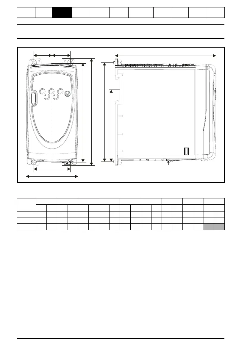
3 Mechanical Installation
Figure 3-1 Commander SK dimensions
Mounting holes: 4 x M4 holes
Table 3-1 Commander SK dimensions
On size A, the mounting feet are equal distance from the centre line of the drive.
On size B and C, the mounting feet are not an equal distance from the centre line of the
drive, hence the Ca and Cb dimensions.
*Size C is not DIN rail mountable.
ABF
C
D
E
G
a
b
Drive
size
ABCCaCbDEFG*
mm in mm in mm in mm in mm in mm in mm in mm in mm in
A 140 5.51 154 6.06 53 2.09 26.5 1.04 26.5 1.04 75 2.95 145 5.71 143 5.63 86.3 3.40
B 190 7.48 205 8.07 55 2.17 23.5 0.93 31.5 1.24 85 3.35 156 6.14 194 7.64 155.5 6.12
C 240 9.45 258 10.16 70.5 2.78 31 1.22 39.5 1.56 100 3.94 173 6.81 244 9.61