34 Commander SK Getting Started Guide
www.controltechniques.com Issue Number: 1
Safety
Information
Rating
Data
Mechanical
Installation
Electrical
Installation
Keypad and
Display
Parameters
Quick Start
Commissioning
Diagnostics Options
Parameter
List
UL Listing
Information
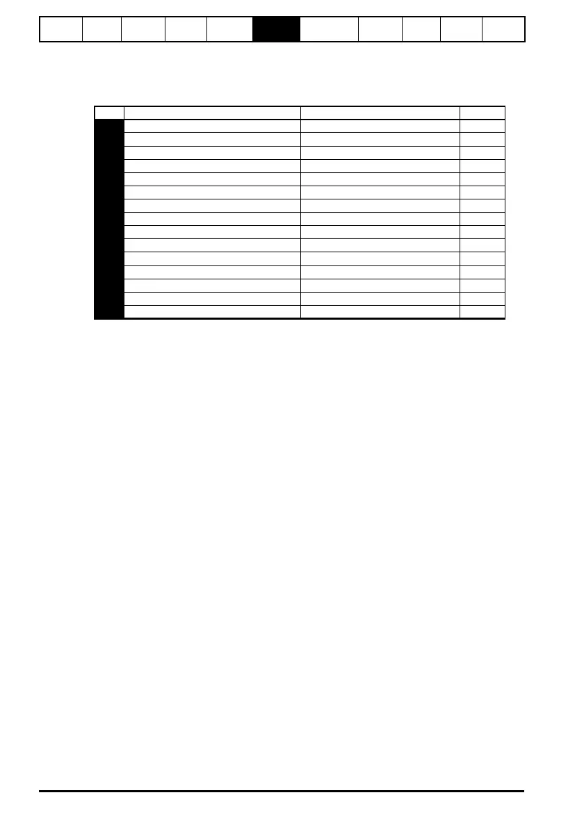
6.4 Diagnostic parameters
The following read only (RO) parameters can be used as an aid to fault diagnosis on the
drive. See Figure 8-1 Diagnostics logic diagram on page 40.
No Function Range Type
81 Reference selected ±Pr 02 Hz RO
82 Pre-ramp reference ±Pr 02 Hz RO
83 Post-ramp reference ±Pr 02 Hz RO
84 DC bus voltage 0 to Drive maximum VDC RO
85 Motor frequency ±Pr 02 Hz RO
86 Motor voltage 0 to Drive rating V RO
87 Motor speed ±9999 rpm RO
88 Motor current ±Drive maximum A RO
89 Motor active current ±Drive maximum A RO
90 Digital I/O readword 0 to 95 RO
91 Reference on indicator OFF (0) or On (1) RO
92 Reverse selected indicator OFF (0) or On (1) RO
93 Jog selected indicator OFF (0) or On (1) RO
94 Analog input 1 0 to 100 % RO
95 Analog input 2 0 to 100 % RO