40 Commander SK Getting Started Guide
www.controltechniques.com Issue Number: 1
Safety
Information
Rating
Data
Mechanical
Installation
Electrical
Installation
Keypad
and Display
Parameters
Quick Start
Commissioning
Diagnostics
Options
Parameter
List
UL Listing
Information
Table 8-1 DC bus voltages
Table 8-2 Alarm warnings
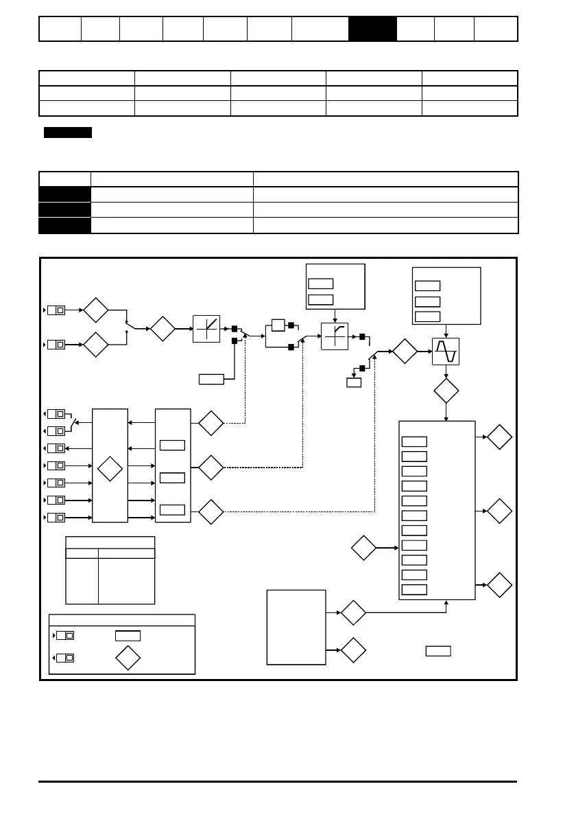
Figure 8-1 Diagnostics logic diagram
Cooling fan control (size B and C only)
As default, the cooling fan is controlled by the drives heatsink temperature. If the
heatsink temperature is below 75°C, the heatsink fan will remain off, if the heatsink
temperature rises above 75°C, the heatsink fan will switch on until the heatsink
temperature falls below 65°C.
For further details, see the Commander SK Advanced User Guide.
Drive voltage rating UV Trip UV Reset Braking level OV trip
200V 175 215 * 390 415
400V 330 425 * 780 830
* These are the absolute minimum DC voltages the drives can be supplied by.
NOTE
Display Condition Solution
OUL.d I x t overload Reduce motor current
hot Heatsink/IGBT temperature high Reduce ambient temperature or reduce motor current
br.rS Braking resistor overload
See
Commander SK Advanced User Guide
Analog inputs
94
95
81
Analog input 1 (%)
Analog input 2 (%)
Digital I/O
XX
Digital I/O
Read
word
Pr
90
Sequencer
92
93
91
Jog
selected
Reverse
selected
Reference
on
X-1
1
0
0
1
0
1
0Hz
82
Pre-ramp
reference (Hz)
84
DC bus
voltage
42
41
40
39
38
37
32
09
08
07
06
Motor rated
current
Motor rated
speed
Motor rated
voltage
Motor power
factor
Variable torque
select
Switching
frequency
Autotune
Motor rated
frequency
No. of poles
Voltage
mode select
Voltage
boost
Motor control
03
Acceleration
rate
Deceleration
rate
Ramps
02
01
Minimum
speed
Maximum
speed
Speed clamps
83
Post-ramp
reference
(Hz)
85
Motor
frequenc
86
Motor
voltage
87
Motor
speed
rpm
88
89
Motor active
current
Motor current
Current
measurement
15
Jog
reference
Digital I/O read word Pr
90
Terminal Binary value for XX
B3 1
B4 2
B5 4
B6 8
B7 16
T6/T5 64
Reference
selected (Hz)
04
T2
T4
T6
T5
B3
B4
B5
B6
B7
XX
XX
Key
Read-write (RW)
parameter
Read-only (RO)
parameter
Input
terminals
Output
terminals
B3
B4
11
12
Start/stop
logic select
Brake
enable
31
Stopping
mode
Ramp mode
30
10
Parameter
access