Safety
Information
Product
Information
Mechanical
Installation
Electrical
Installation
Keypad and
Display
Parameters
Quick Start
Commissioning
Diagnostics Options Parameter List
UL Listing
Information
34 Commander SK Size 2 to 6 Getting Started Guide
www.controltechniques.com Issue Number: 2
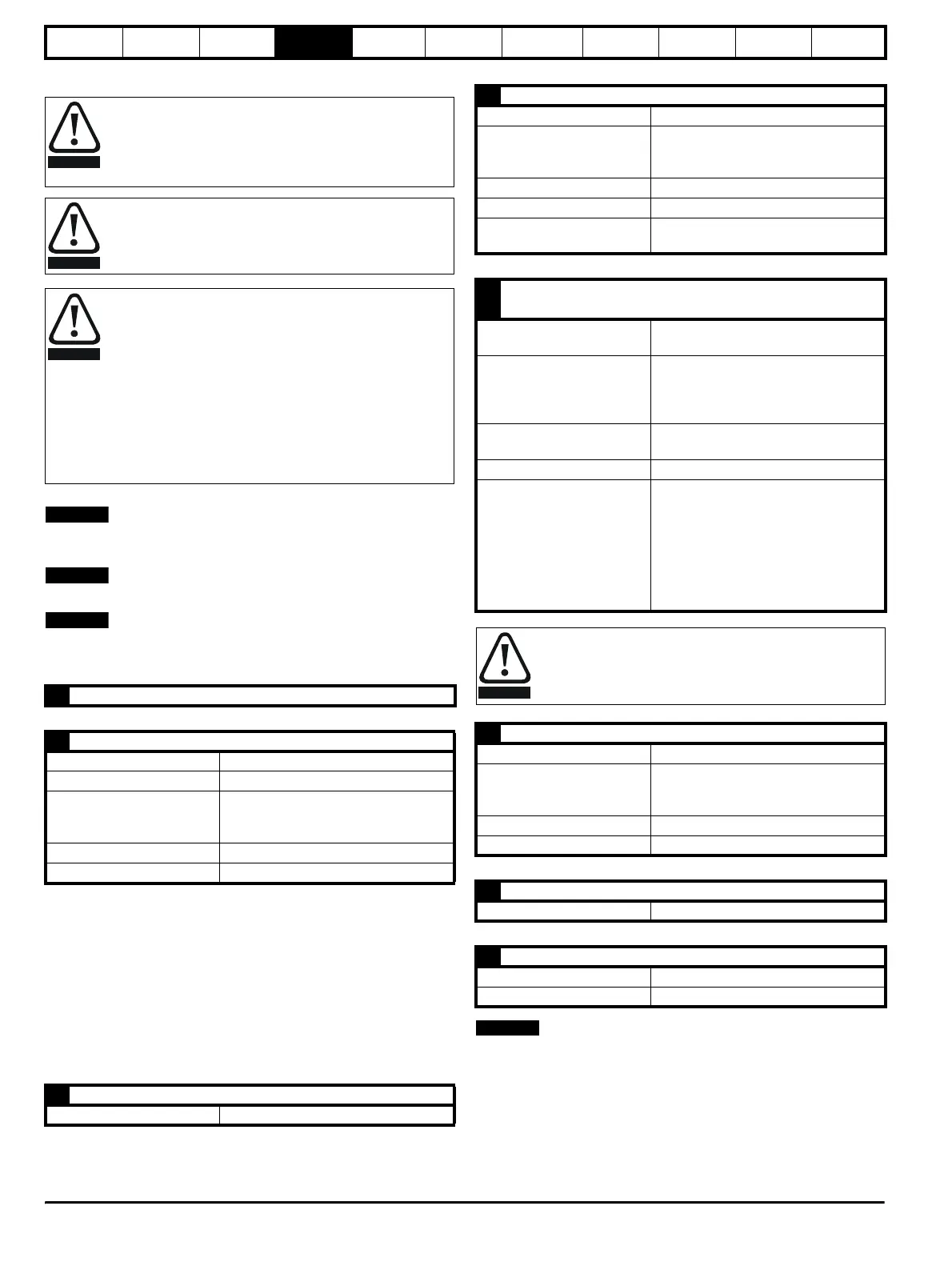
4.5 Control terminals I/O specification
See Pr 05 on page 38 (Drive configuration) for terminal connection / set-
up diagrams and details.
The digital inputs are positive logic only.
The analogue inputs are unipolar. For information on a bipolar input, see
the Commander SK Advanced User Guide.
0-20: Current input 0 to 20mA (20mA full scale)
20-0: Current input 20 to 0mA (0mA full scale)
4-20: Current input 4 to 20mA with current loop loss (cL1) trip
(20mA full scale)
20-4: Current input 20 to 4mA with current loop loss (cL1) trip
(4mA full scale)
4-.20: Current input 4 to 20mA with no current loop loss (cL1) trip
(20mA full scale)
20-.4: Current input 20 to 4mA with no current loop loss (cL1) trip
(4mA full scale)
VoLt: 0 to 10V input
The total available current from the digital output plus the +24V output is
100mA.
The control circuits are isolated from the power circuits in the
drive by basic insulation (single insulation) only. The installer
must ensure that the external control circuits are insulated from
human contact by at least one layer of insulation (supplementary
insulation) rated for use at the AC supply voltage.
If the control circuits are to be connected to other circuits
classified as Safety Extra Low Voltage (SELV) (e.g. to
personal computer), an additional isolating barrier must be
included in order to maintain the SELV classification.
The above warnings also apply to the PCB edge connector
for the optional Solutions Modules. To allow a Solutions
Module to be fitted to Commander SK, a protective cover
must be removed to allow access to the PCB edge connector.
See Figure 3-22 on page 27. This protective cover provides
protection from direct contact of the PCB edge connector by
the user. When this cover is removed and a Solutions Module
fitted, the Solutions Module provides the protection from
direct contact by the user. If the Solutions Module is then
removed, this PCB edge connector becomes exposed. The
user is required to provide protection in this case, to protect
against direct contact of this PCB edge connector.
T1 0V common
T2 Analogue input 1 (A1), either voltage or current (see Pr 16)
Voltage: Current input 0 to 10V: mA as parameter range
Parameter range 4-20, 20-4, 0-20, 20-0, 4-.20, 20-.4, VoLt
Scaling
Input range automatically scaled to Pr
01 Minimum set speed / Pr 02 Maximum
set speed
Input impedance 200Ω (current): 100kΩ (voltage)
Resolution 0.1%
T3 +10V reference output
Maximum output current 5mA
WARNING
WARNING
WARNING
NOTE
NOTE
NOTE
T4 Analogue input 2 (A2), either voltage or digital input
Voltage: Digital input 0 to +10V: 0 to +24V
Scaling (as voltage input)
Input range automatically scaled to Pr
01 Minimum set speed / Pr 02 Maximum
set speed
Resolution 0.1%
Input impedance 100kΩ (voltage): 6k8 (digital input)
Normal threshold voltage (as
digital input)
+10V (positive logic only)
T5
Status relay - Drive healthy (Normally open)
T6
Contact voltage rating
240Vac
30Vdc
Contact maximum current
rating
2Aac 240V
4Adc 30V resistive load (2A 35Vdc for
UL requirements).
0.3Adc 30V inductive load (L/R=40ms)
Contact minimum
recommended rating
12V 100mA
Contact isolation 1.5kVac (over voltage category II)
Operation of contact (drive
healthy - default condition)
OPEN
AC supply removed from drive
AC supply applied to drive with drive in
tripped condition
CLOSED
AC supply applied to drive with drive in a
'ready to run' or 'running' condition (not
tripped)
Provide fuse or over-current protection in status relay circuit.
B1 Analogue voltage output - Motor speed
Voltage output 0 to +10V
Scaling
0V represents 0Hz/rpm output
+10V represents the value in Pr 02
Maximum set speed
Maximum output current 5mA
Resolution 0.1%
B2 +24V output
Maximum output current 100mA
B3 Digital output - Zero speed
Voltage range 0 to +24V
Maximum output current 50mA at +24V (current source)
WARNING
NOTE