Safety
Information
Product
Information
Mechanical
Installation
Electrical
Installation
Keypad and
Display
Parameters
Quick Start
Commissioning
Diagnostics Options Parameter List
UL Listing
Information
Commander SK Size 2 to 6 Getting Started Guide 31
Issue Number: 2 www.controltechniques.com
On Commander SK size 4, 5 and 6, the supply and motor ground
connections are made using an M10 bolt at the top (supply) and bottom
(motor) of the drive.
Figure 4-6 Size 4, 5 and 6 ground connections
The supply and motor ground connections to the drive are connected
internally by a copper conductor with a cross-sectional area given below:
size 4: 19.2mm2 (0.03in
2
, or slightly bigger than 6 AWG)
size 5: 60mm2 (0.09in
2
, or slightly bigger than 1 AWG)
size 6: 75mm2 (0.12in
2
, or slightly bigger than 2/0 AWG)
This connection is sufficient to provide the ground (equipotential
bonding) connection for the motor circuit under the following conditions:
If the necessary conditions are not met, an additional ground connection
must be provided to link the motor circuit ground and the supply ground.
4.2 Heatsink fan
4.2.1 Heatsink fan operation
The Commander SK is ventilated by an internal heatsink mounted fan.
The fan housing forms a baffle plate, channelling the air through the
heatsink chamber. Thus, regardless of the mounting method (surface or
through-panel mounting), the fitting of additional baffle plates is not
required.
Ensure the minimum clearances around the drive are maintained to
allow air to flow freely.
The heatsink fan on Commander SK size 2 is a dual speed fan and on
size 3 to 6, it is a variable speed fan. The drive controls the speed at
which the fan runs based on the temperature of the heatsink and the
drive's thermal model system. The Commander SK size 3 to 6 is also
fitted with a single speed fan to ventilate the capacitor bank.
The heatsink fan on the Commander SK size 2 to 5 is supplied internally by
the drive. The heatsink fan on the size 6 requires an external +24Vdc power
supply.
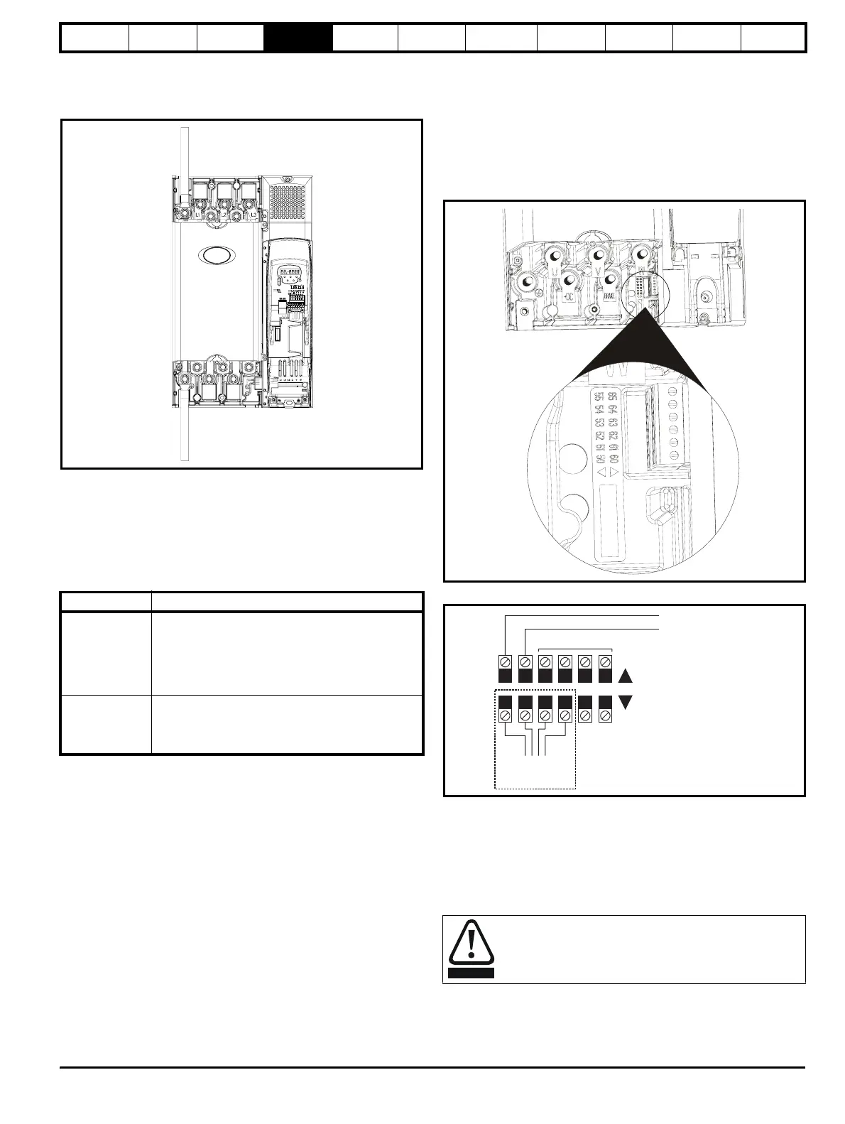
4.2.2 Heatsink fan supply
The heatsink fan on size 6 requires an external +24Vdc supply. The
connections for the heatsink fan supply must be made to the upper
terminal connector near to the W phase output on the drive. See Figure
4-7
for the position of the heatsink fan supply connector.
Figure 4-7 Location of size 6 heatsink fan supply connections
Figure 4-8 Size 6 heatsink fan supply connections
The heatsink fan supply requirements are as follows:
Nominal voltage: 24Vdc
Minimum voltage: 23.5Vdc
Maximum voltage: 27Vdc
Current drawn: 3.3A
Recommended power supply: 24V, 100W, 4.5A
Recommended fuse: 4A fast blow (I
2
t less than 20A
2
s)
To standard Conditions
IEC 60204-1 &
EN 60204-1
Supply phase conductors having cross-sectional
area not exceeding:
size 4: 38.4mm
2
size 5: 120mm
2
size 6: 150mm
2
NFPA 79
Supply protection device rating not exceeding:
size 4: 200A
size 5: 600A
size 6: 1000A
Supply
ground
Motor
ground
The AC supply to the drive must be fitted with suitable
protection against overload and short circuits. Failure to
observe this requirement will cause risk of fire. See section
2.3 Rating Data on page 10 for fuse data.
55 54 53 52 51 50
65 64 63 62 61 60
To the heatsink fan
Pre-wired internally
Not used
0V
24V heatsink fan supply
Upper terminal connector
Lower terminal connector
WARNING