Safety
Information
Product
Information
Mechanical
Installation
Electrical
Installation
Keypad and
Display
Parameters
Quick Start
Commissioning
Diagnostics Options Parameter List
UL Listing
Information
Commander SK Size 2 to 6 Getting Started Guide 25
Issue Number: 2 www.controltechniques.com
3.3 Mounting brackets
3.3.1 Fitting of the Commander SK mounting
brackets on size 4, 5 and 6
Commander SK size 4,5 and 6 use the same mounting brackets for
surface and through-panel mounting.
The mounting bracket has a long section and short section.
Figure 3-17 Size 4, 5 and 6 mounting bracket
The mounting bracket must be fitted in the correct orientation with the
long section inserted into or attached to the drive and the short section
attached to the backplate. Figure 3-18 shows the orientation of the
mounting bracket when the drive is surface mounted and through-panel
mounted.
Figure 3-18 Orientation of the size 4, 5 and 6 mounting bracket
Commander SK size 5 and 6 also requires two top mounting brackets
when the drive is surface mounted. The two brackets should be fitted to
the top of the drive as shown in Figure 3-19.
Figure 3-19 Location of top surface mounting brackets for size 5 and 6
The maximum torque setting for the screws into the drive chassis is
10Nm (7.4 lb ft).
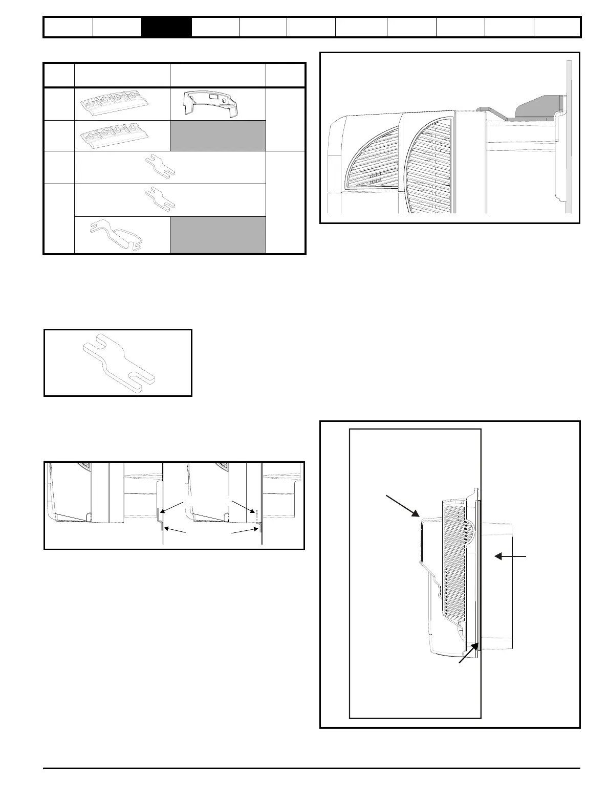
3.4 IP Rating (Ingress Protection)
3.4.1 Commander SK size 2, 3 and 4
The Commander SK size 2, 3 and 4 is rated to IP20 pollution degree 2
(dry, non-conductive contamination only) and/or NEMA 1. However, it is
possible to configure the drive to achieve IP54 rating and/or NEMA 12 at
the rear of the heatsink for through-panel mounting (some current de-
rating is required for size 2).
This allows the front of the drive, along with various switchgear, to be
housed in an IP54 and/or NEMA 12 enclosure with the heatsink
protruding through the panel to the external environment. Thus, the
majority of the heat generated by the drive is dissipated outside the
enclosure maintaining a reduced temperature inside the enclosure. This
also relies on a good seal being made between the heatsink and
backplate using the gasket provided.
Figure 3-20 Example of IP54 and/or NEMA 12 rating layout
In order to achieve the high IP rating at the rear of the heatsink with
Commander SK size 2, it is necessary to seal a heatsink vent by fitting
the IP54 insert as shown in Figure 3-21 on page 26.
Model
size
Surface Through-panel
Hole
size
2x2x1
6.5mm
(0.256in)
3x2
4
x4
8.5mm
(0.335in)
5 & 6
x4
x2
hort sectio
Long section
Short section
Long section
IP20
and/or
NEMA1
IP54 and/or NEMA 12
enclosure
Drive with
IP54 insert
and IP54
fan fitted
Gasket
seal