Safety
Information
Product
Information
Mechanical
Installation
Electrical
Installation
Keypad and
Display
Parameters
Quick Start
Commissioning
Diagnostics Options Parameter List
UL Listing
Information
46 Commander SK Size 2 to 6 Getting Started Guide
www.controltechniques.com Issue Number: 2
0: Disabled
1: Detect positive and negative frequencies
2: Detect positive frequencies only
3: Detect negative frequencies only
If the drive is to be configured in fixed boost mode (Pr 41 = Fd or SrE) with catch a spinning motor software enabled, an autotune (see Pr 38 on page
47) must be carried out to measure the motor’s stator resistance beforehand. If a stator resistance is not measured, the drive may trip on OV and
OI.AC while trying to catch a spinning motor.
dig: Digital input
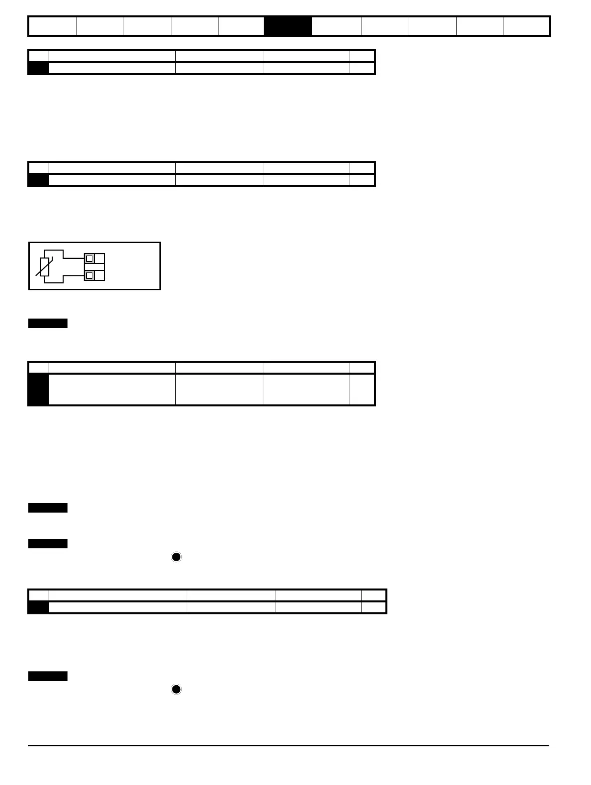
th: Motor thermistor input, connect as per diagram below
Fr: Frequency input. See Commander SK Advanced User Guide.
Fr.hr: High resolution frequency input. See Commander SK Advanced User Guide.
Figure 6-11
Trip resistance: 3kΩ
Reset resistance: 1k8
If Pr 34 is set to th so that terminal B7 is used as a motor thermistor, the functionality of terminal B7 as set-up with Pr 05, drive configuration, will be
disabled.
n=0: At zero speed
At.SP: At speed
Lo.SP: At minimum speed
hEAL: Drive healthy
Act: Drive active
ALAr: General drive alarm
I.Lt: Current limit active
At.Ld: At 100% load
USEr: User programmable
This parameter is automatically changed by the setting of Pr 12. When Pr 12 automatically controls the setting of this parameter, this parameter
cannot be changed.
A change to Pr 35 is set by pressing the MODE key on exit from parameter edit mode.
See the Commander SK Advanced User Guide.
Fr: Voltage proportional to motor speed
Ld: Voltage proportional to motor load
A: Voltage proportional to output current
Por: Voltage proportional to output power
USEr: User programmable
A change to Pr 36 is set by pressing the MODE key on exit from parameter edit mode.
See the Commander SK Advanced User Guide.
No Function Range Defaults Type
33 Catch a spinning motor select 0 to 3 0 RW
No Function Range Defaults Type
34 Terminal B7 mode select dig, th, Fr, Fr.hr dig RW
0V
Motor thermistor
input
T1
B7
No Function Range Defaults Type
35 Digital output control (terminal B3)
n=0, At.SP, Lo.SP,
hEAL, Act, ALAr, I.Lt,
At.Ld, USEr
n=0 RW
No Function Range Defaults Type
36 Analogue output control (terminal B1) Fr, Ld, A, Por, USEr Fr RW
NOTENOTE
NOTENOTE
NOTENOTE
M
NOTENOTE
M