139
Options and Accessories
STI-24IO Interface
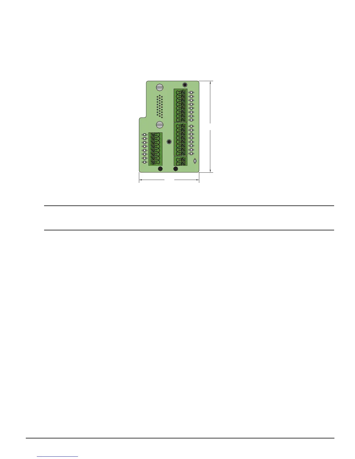
The STI-24IO interface for the Epsilon EP-I drives, see figure 116, allows access to all digital input and output signals. The
STI-24IO board mounts directly to the Epsilon EP-I drive Input/Output Connection (J3) and away from any high voltage
wiring.
Figure 116: Dimensions of the STI-24IO Board
Wiring should be done with consideration for future troubleshooting and repair. All wiring should be either color coded
and/or tagged with industrial wire tabs. Low voltage wiring should be routed away from high voltage wiring.
+24V
0V
1
2
3
4
5
6
7
8
OUTPUTS
1
2
3
4
5
6
7
8
INPUTS
9
10
11
12
13
14
15
EN
3.2
2.1