140
Epsilon EP-I Indexing Drive and FM-2 Indexing Module Reference Manual
STI-EIO Interface
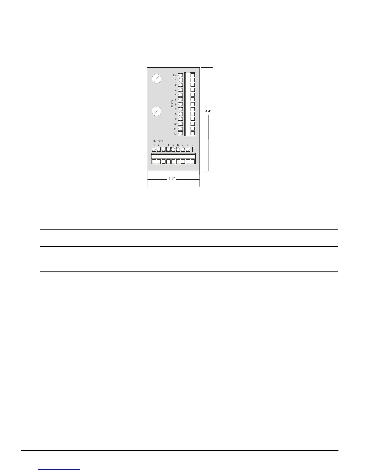
The STI-EIO interface for the Epsilon Classic drives, see figure 117, allows access to all digital input and output signals. The
STI-EIO board mounts directly to the Epsilon drive’s Input/Output Connection (J3) and away from any high voltage wiring.
Figure 117: Dimensions of STI-EIO Board
Shield connection points are connected to the shell of the 44-pin “D” connector on the STI-EIO.
The STI-EIO wire range is #18 to 24 AWG stranded insulated wire.
Wiring should be done with consideration for future troubleshooting and repair. All wiring should be either color coded
and/or tagged with industrial wire tabs. Low voltage wiring should be routed away from high voltage wiring.