72
Epsilon EP-I Indexing Drive and FM-2 Indexing Module Reference Manual
Pulse Mode
In Pulse mode, the drive will receive pulses which are used to control the position and velocity of the motor.
There are three pulse interpretations associated with Pulse mode: Pulse/Pulse, Pulse/Direction and Pulse/Quadrature. These
selections determine how the input pulses are interpreted by the drive.
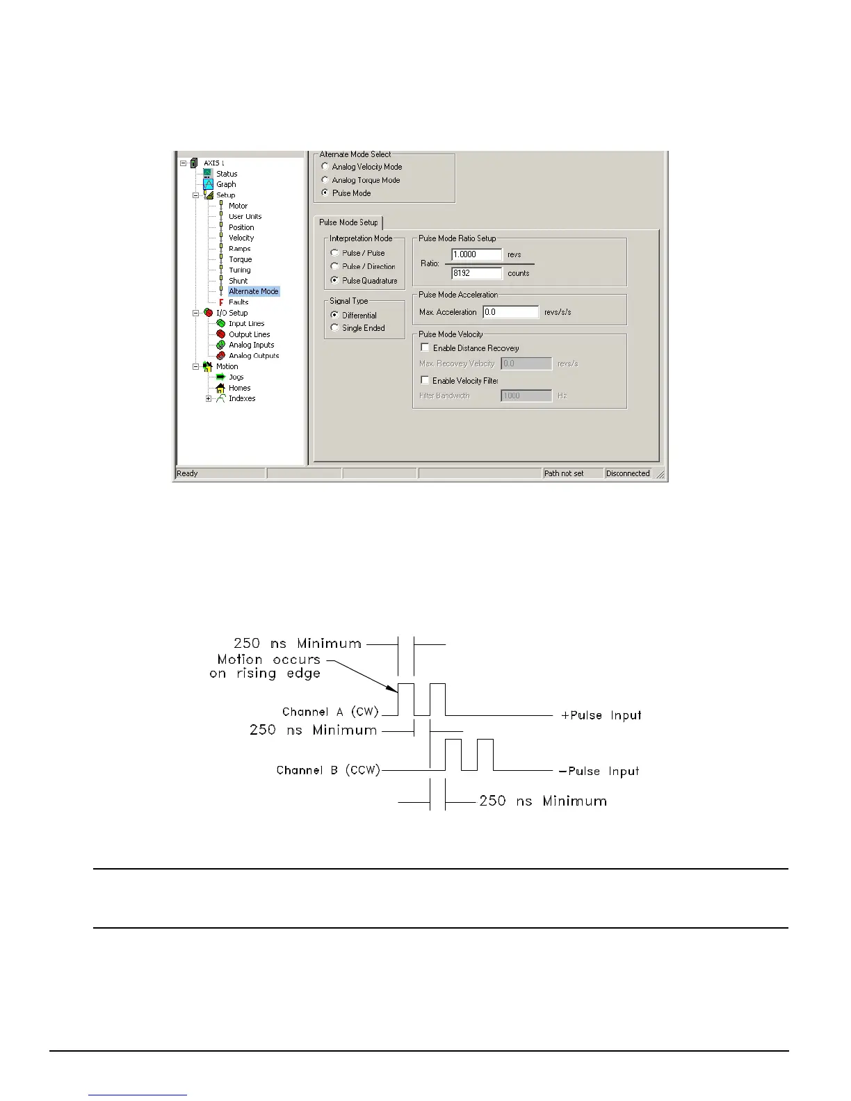
Figure 74: Alternate Mode - Pulse Mode
Interpretation Mode Group
Pulse/Pulse Interpretation
In Pulse/Pulse interpretation, pulses received on the A channel are interpreted as positive changes to the Pulse Position Input.
Pulses received on the B channel are interpreted as negative changes to the Pulse Position Input.
Figure 75: Pulse/Pulse Signals, Differential Inputs
If a travel limit is encountered when in Pulse mode, the user must exit alternate mode and either jog or index off of the
travel limit sensor before continuing.
Pulse/Direction Interpretation
In Pulse/Direction interpretation, pulses are received on the A channel and the direction is received on the B channel. If the
B is high, pulses received on the A are interpreted as positive changes to the Pulse Position Input. If the B is low, pulses
received on the A are interpreted as negative changes to the Pulse Position Input.