*
M’Ax Advanced User Guide 24
Issue Number: 4 www.controltechniques.com
Therefore:
Refer to above text.
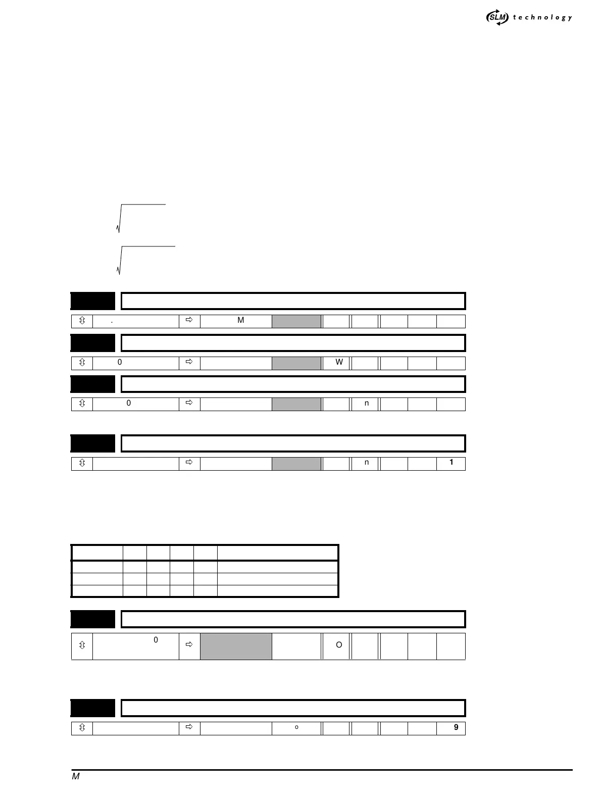
The drive holds three gain buffers, any buffer can be selected for use by the speed controller with parameter 3.16.
0 = Terminal input control
1 = PID buffer 1 is selected
2 = PID buffer 2 is selected
3 = PID buffer 3 is selected
Summary of effected parameters when switching P.I.D buffers
Total inertia driven by the motor is the sum of: Load Inertia + Motor Inertia.
This is required to calculate the PID gains.
The stiffness angle is the required angular displacement when the drive delivers a torque producing current equivalent to the drive rated
3.13 Speed-loop proportional gain. Kp2
ô
0.0000 ~ 0.3000
ð
SLM RW Uni
3.14 Speed-loop integral gain. Ki2
ô
0.0000 ~ 30.000
ð
SLM RW Uni
3.15 Speed-loop derivative gain. Kd2
ô
0.0000 ~ 0.1000
ð
SLM RW Uni
3.16 Speed-loop PID gain selector
ô
0~3
ð
1 RW Uni 0.12
Pr 3.16
K
P
K
I
K
D
K
C
Current demand filter cut off
1 3.10 3.11 3.12 4.07 4.12
2 3.13 3.14 3.15 4.24 4.23
3 3.60 3.61 3.62 4.28 4.27
3.18 Total inertia
ô
0.1 ~ 6000.0
0.00001 ~ 0.6
ð
Kgcm
2
Kgm
2
RO Uni 0.11
3.19 Stiffness angle
ô
0.0 ~ 30.0
ð
6.0
o
RW Uni 0.09
K
c
200
100
----------
9.5× 19==
K
b
4
π
---
const==
K
o
19 1.6× 30.4==
J 0.00076 0.00224+ 0.003==
α 6=
K
i
22.5
6
-----------
3.75==
K
p
2
0.003 3.75×
4
π
---
30.4×
--------------------------------- 0.034==
K
d
1
2
---
0.003
4
π
---
30.4 3.75××
--------------------------------------- 0.0023==