*
M’Ax Advanced User Guide 26
Issue Number: 4 www.controltechniques.com
Difference in between the encoder marker and 0 position at parameter 3.29. On power up, SLM uses single cycle Sin-Cos output to find
absolute shaft position. This measurement has a maximum of ±3° error. After passing through Marker pulse this offset is calculated.
This is offset in between SLM marker pulse and shaft key, set by motor manufacturer.
User specified marker offset for encoder simulation.
Range selectable from 100 lines per revolution to 8192 lines per revolution
Set this parameter to 0 enables 16384 pulses per revolution
When modified, in order for the new value to take effect, a power-down and up again is required.
0 = Quadrature A & B differential outputs (Including Marker pulses)
1 = Frequency & Directional differential outputs (Including Marker pulses)
Allows the user to select which gain buffer is required. Buffer selection:
x = don't care conditions
Refer to parameters 3.10, 3.11, 3.12
Used to indicate which PID buffer currently in use.
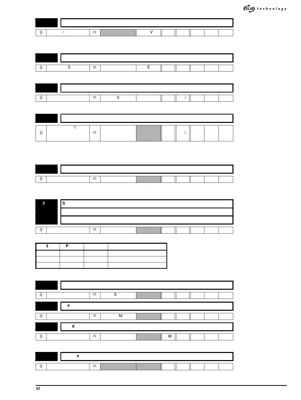
3.52 Z marker pulse offset
ô
0 ~ 65535
ð
REV RO Uni
3.53 Shaft key offset
ô
0 ~ 65535
ð
SLM REV RO Uni
3.54 Zero offset
ô
0~180
ð
0
o
RW Uni
3.55 Number of simulated encoder lines
ô
0, 100 ~ 8192
selectable
& 16384
ð
4096 RW Uni R
3.56 F/D mode select
ô
0~1
ð
0 RW Bit
3.57 Speed-loop PID Buffer 1 select
3.58 Speed-loop PID Buffer 2 select
3.59 Speed-loop PID Buffer 3 select
ô
0~1
ð
0 RW Bit
Pr3.57 Pr3.58 Pr3.59 Gain Buffer selected, Pr3.16
1xx 1
01x 2
001 3
3.60 Speedloopproportionalgain.Kp3
ô
0.0000 ~ 0.3000
ð
SLM RW Uni
3.61 Speed loop integral gain. Ki3
ô
0.0000 ~ 30.000
ð
SLM RW Uni
3.62 Speedloopderivativegain.Kd3
ô
0.0000 ~ 0.1000
ð
SLM RW Uni
3.63 SpeedloopPIDbufferinuseindicator
ô
0~3
ð
RO Uni