*
51 M’Ax Advanced User Guide
www.controltechniques.com Issue Number: 4
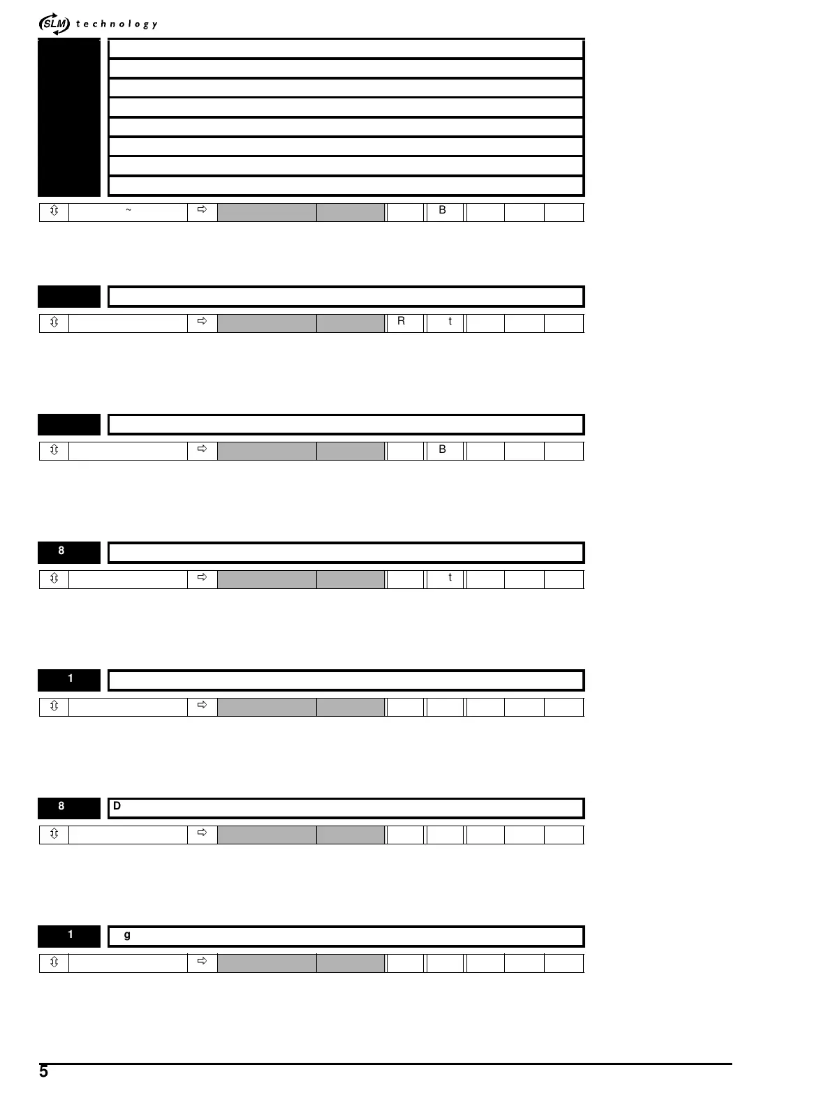
These parameters indicate the input state of the terminals.
0=In-active
1=Active
This parameter indicates if the hardware enable contact is closed. If the hardware enable contact is open the drive will display “Inh”.Ifthe
hardware enable is closed, the drive will display either “Rdy”, “StP”,or“run”.
0=In-active
1=Active
This invert parameter is used to change the sense of terminal 10 on the Digital I/O port. Setting this parameter to 1 causes the input sense to
the destination parameter to be inverted.
0=Notinverted
1=Inverted
This invert parameter is used to change the sense of terminal 9 on the Digital I/O port. Setting this parameter to 1 causes the input sense to
the destination parameter to be inverted.
0=Notinverted
1=Inverted
This invert parameter is used to change the sense of terminal 8 on the Digital I/O port. Setting this parameter to 1 causes the input sense to
the destination parameter to be inverted.
0=Notinverted
1=Inverted
This invert parameter is used to change the sense of terminal 7 on the Digital I/O port. Setting this parameter to 1 causes the input sense to
the destination parameter to be inverted.
0=Notinverted
1=Inverted
This invert parameter is used to change the sense of terminal 1 on the Digital I/O port. Setting this parameter to 1 causes the input sense to
the destination parameter to be inverted.
0=Notinverted
1=Inverted
8.01 Digital input 1 state indicator - Digital I/O terminal 10
8.02 Digital input 2 state indicator - Digital I/O terminal 9
8.03 Digital input 3 state indicator - Digital I/O terminal 8
8.04 Digital input 4 state indicator - Digital I/O terminal 7
8.05 Digital input 5 state indicator - Digital I/O terminal 1
8.06 Digital input 6 state indicator - Digital I/O terminal 6
8.07 Digital input 7 state indicator - Digital I/O terminal 13
8.08 Digital input 8 state indicator - Digital I/O terminal 8
ô
0~1
ð
RO Bit P
8.09 Hardware enable indicator - MCIEIA 485 / Standalone terminal 3
ô
0~1
ð
RO Bit P 0.01
8.11 Digital Input 1 invert
ô
0~1
ð
RO Bit P
8.12 Digital Input 2 invert
ô
0~1
ð
RO Bit P
8.13 Digital Input 3 invert
ô
0~1
ð
RO Bit P
8.14 Digital Input 4 invert
ô
0~1
ð
RO Bit P
8.15 Digital Input 5 invert
ô
0~1
ð
RO Bit P