SM-Resolver User Guide 27
Issue Number: 4 www.controltechniques.com
Resolvers with the following numbers of poles can be used with the Solutions Module.
0: 2POLE
1: 4POLE
2: 6POLE
3 to 11: 8POLE
A 2 pole resolver can be selected as drive speed feedback with a motor with any
number of poles. A resolver with a number of poles greater than 2 can only be used with
a motor with the same number of poles. If the number of resolver poles is set up
incorrectly and the resolver is selected as the drive speed feedback for motor control
Solutions Module error 11 is produced.
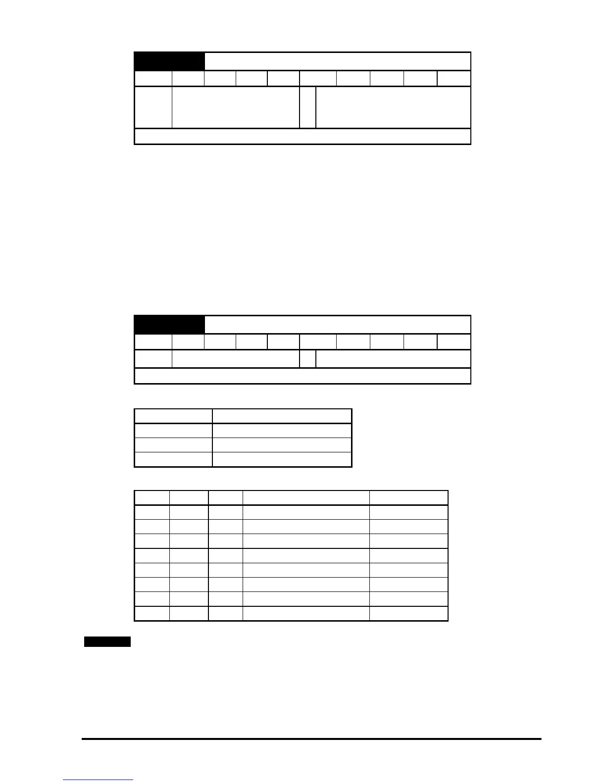
Trips can be enabled/disabled using Pr x.17 as follows:
The binary sum defines the level of error detection as below:
x.15 Resolver poles
RW Uni US
Ú
2POLE (0), 4POLE (1),
6POLE (2), 8POLE (3 to
11)
Ö
2POLE (0)
Update rate: Background read
x.17 Error detection level
RW Uni US
Ú
0 to 7
Ö
1
Update rate: Background read
Bit Function
0 Wire break detect
1 Not used
2 Not used
Bit 2 Bit 1 Bit 0 Error detection level Value in Pr x.17
0 0 0 Error detection disabled 0
0 0 1 Wire break detect 1
0 1 0 Error detection disabled 2
0 1 1 Wire break detect 3
1 0 0 Error detection disabled 4
1 0 1 Wire break detect 5
1 1 0 Error detection disabled 6
1 1 1 Wire break detect 7
The wire break trip is not activated provided one signal is >1.5Vrms or both are >0.2Vrms
approximately.
NOTE