Safety
Information
Product
Information
Mechanical
Installation
Electrical
Installation
Getting
Started
Menu 0
Running
the motor
Optimisation Macros
Advanced
Parameters
Technical
Data
Diagnostics
UL Listing
Information
Unidrive User Guide 47
Issue Number: 9 www.controltechniques.com
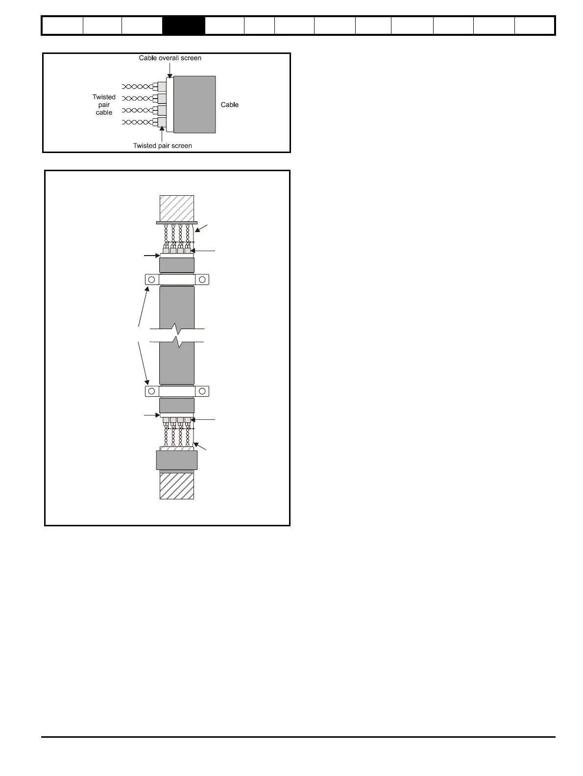
Figure 4-10 Feedback cable, twisted pair
Figure 4-11 Feedback cable connections
To ensure suppression of radio frequency emission,
observe the following:
• Use a cable with an overall shield
• Clamp the overall shield to grounded metallic surfaces at both the
encoder and the drive, as illustrated in Figure 4-11.
Cable
Cable
shield
Twisted
pair
shield
Cable
shield
Twisted
pair
shield
Connection
t m
t
r
onnection
at drive
Ground clamp
on shield
Shield
connection
to 0V
Shield
connection
to 0V