EasyManuals Logo

Control Techniques Unidrive M100 Step-By-Step Guide

Control Techniques Unidrive M100
52 pages
To Next Page IconTo Next Page
To Previous Page IconTo Previous Page
Page #27 background imageLoading...
Page #27 background image
Schritt-für-Schritt-Anleitung Unidrive M200/M201/M300 27
Ausgabenummer: 1
English Français
Deutsch
Italiano Español
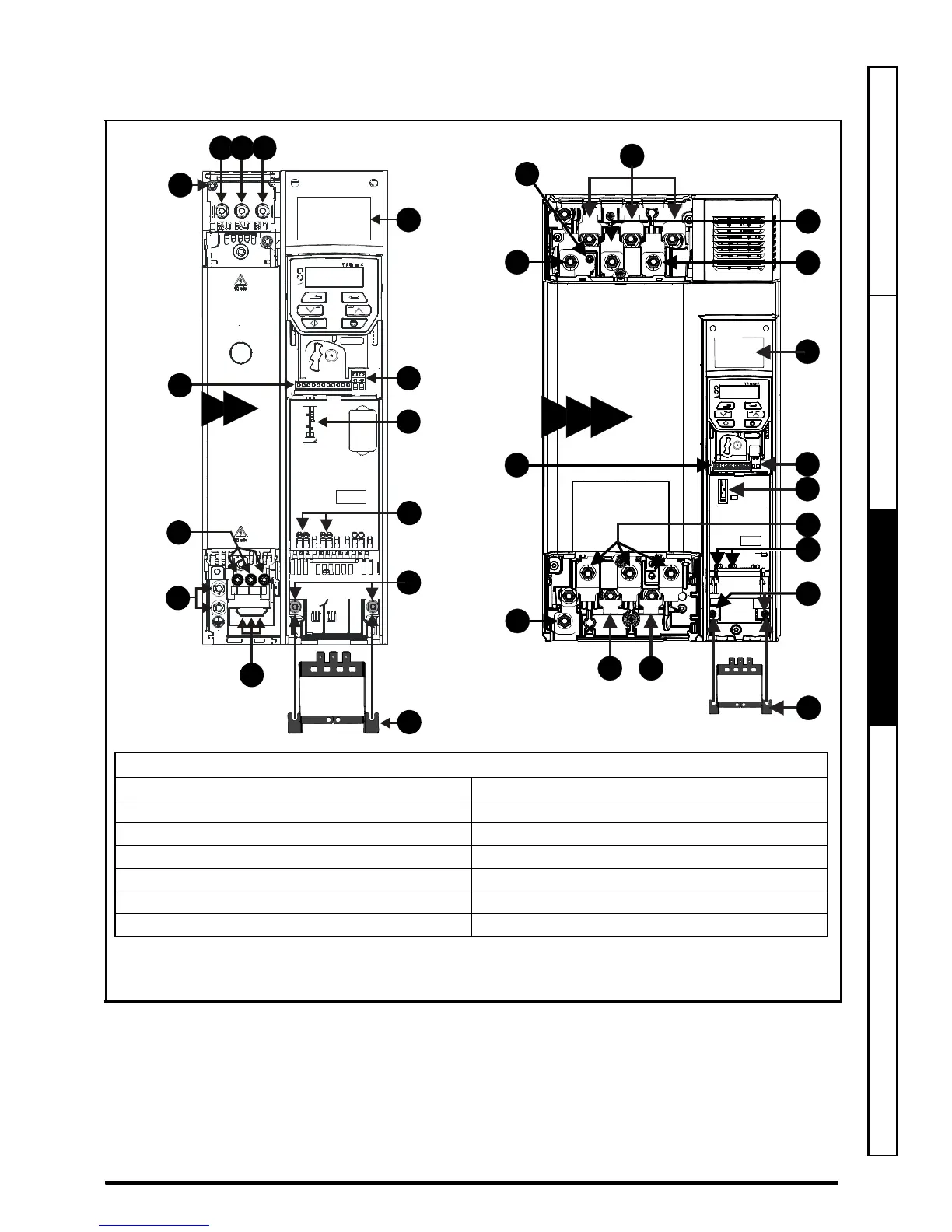
SCHRITT 7: Identifikation der Merkmale des Umrichters
Abbildung 7-1 Anschlussdiagramm
PE
+DC -DC
U
V
W
L1 L2 L3
6
5
5
1
41 42
2
3
4
7
7
8
9
+DC
BRAKE
8
10
11
13
7 8
9
12
5
1
2
7
U V W
5
12
12
12 12
910
8
12
1
1
2
3
13
11
4
5
6
7
6
5
Legende
1. Typenschild 2. Relaisanschlussklemmen
3. Optionsmodul-Steckplatz 1 4. Motoranschlüsse
5. Erdung 6. Netzanschlüsse
7. Steueranschlüsse 8. DC Bus +
9. DC Bus - 10. Anschlussklemmen für den Bremswiderstand
11. Kabelhalterung der Erdungsanschlussklemmen 12. Schraube f. internes EMV-Filter*
13. Safe Torque Off Klemmen (STO)**
* Vor dem Entfernen der Schraube Kapitel 4 des Leistungsmodul-Installationshandbuchs lesen.
** Nur Unidrive M300.

Other manuals for Control Techniques Unidrive M100

Questions and Answers:

Question and Answer IconNeed help?

Do you have a question about the Control Techniques Unidrive M100 and is the answer not in the manual?

Control Techniques Unidrive M100 Specifications

General IconGeneral
BrandControl Techniques
ModelUnidrive M100
CategoryController
LanguageEnglish

Related product manuals