Service Handbook OEB/OES/OGB/OGS
Safety:
When working on the operation module, make sure that the main power
supply is disconnected (an all-pole isolation switch with a minimum contact
opening of 3mm must be located close to the unit- on site) and ensured
against switching on again.
This work should only be performed by a CONVOTHERM trained electrician.
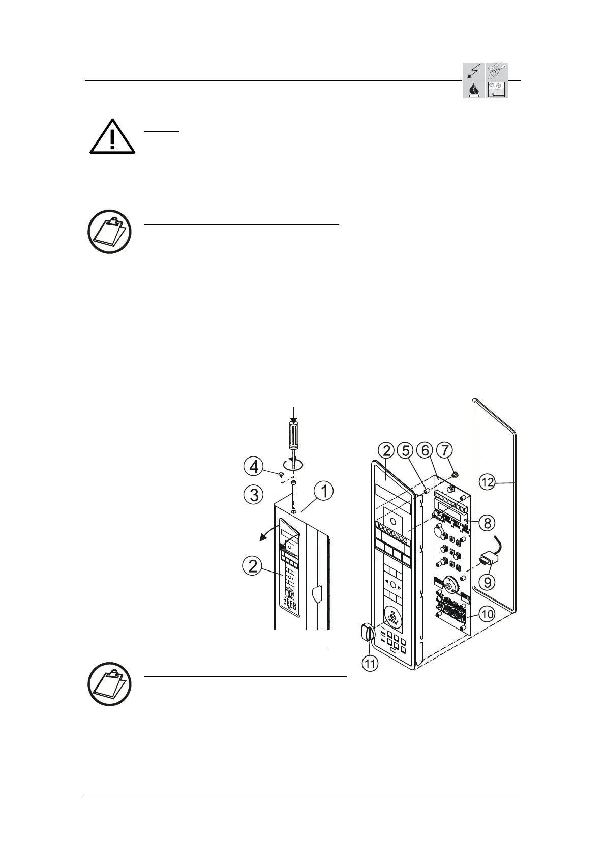
Instructions: Operation module removal
Remove the cap 4 from the hexagon locking screw 3 on the unit top 1.
Turn the hexagon locking screw 3 counterclockwise approx. 12 times.
To release the front plate 2 press the hexagon locking screw 3 as far down as
it will go. By lightly tapping the front part, the front plate 2 will clap out forward.
Lift the front plate 2 downwards out of the holder and lay it next to the unit.
(cable length 1,8m).
Loosen and unplug the 9 pole connector 9 on the back side of the operation
module 6.
Unscrew the 6 knurled nuts 7 and pull out the operation module 6 straight and
evenly from the fastening.
Attention: Don‘t lose distancing bushes 5 and the light guide around the keys
and don‘t damage vacuum cylinders 8 on the side of the display Display
defect!
SW5
8 = Unit top
9 = Front plate
10 = Loc
king screw with
hexagon socket
11 = Cap
12 = Distancing bushes
13 = Operation module (BM)
14 = Knurled nuts
15 = Vacuum cylinders
16 = 9 pole connector to
Control module
17 = Picto module (PM)
18 = Adjustable knob
19 = Sealing frame part no. 7011010
Instructions: Operation module assembly
Place operation module 6 straight and evenly onto the fastening bolts.
Attention: Make sure that the distancing bushes are present 5 and push the
light conductor straight and evenly onto the loop element.
Screw on the 6 knurled bushes 7 and tighten.
Plug in the 9 pole connector 9 on the back side of the operation module 6 and
tighten.
Check the sealing frame part no. 7011010 and replace if damaged.
AS/11-2011 6_01e_Electronic Control Board installation_c
Page 2 / 8
 Loading...