EM 6400 User Manual v03.02. – d12
18
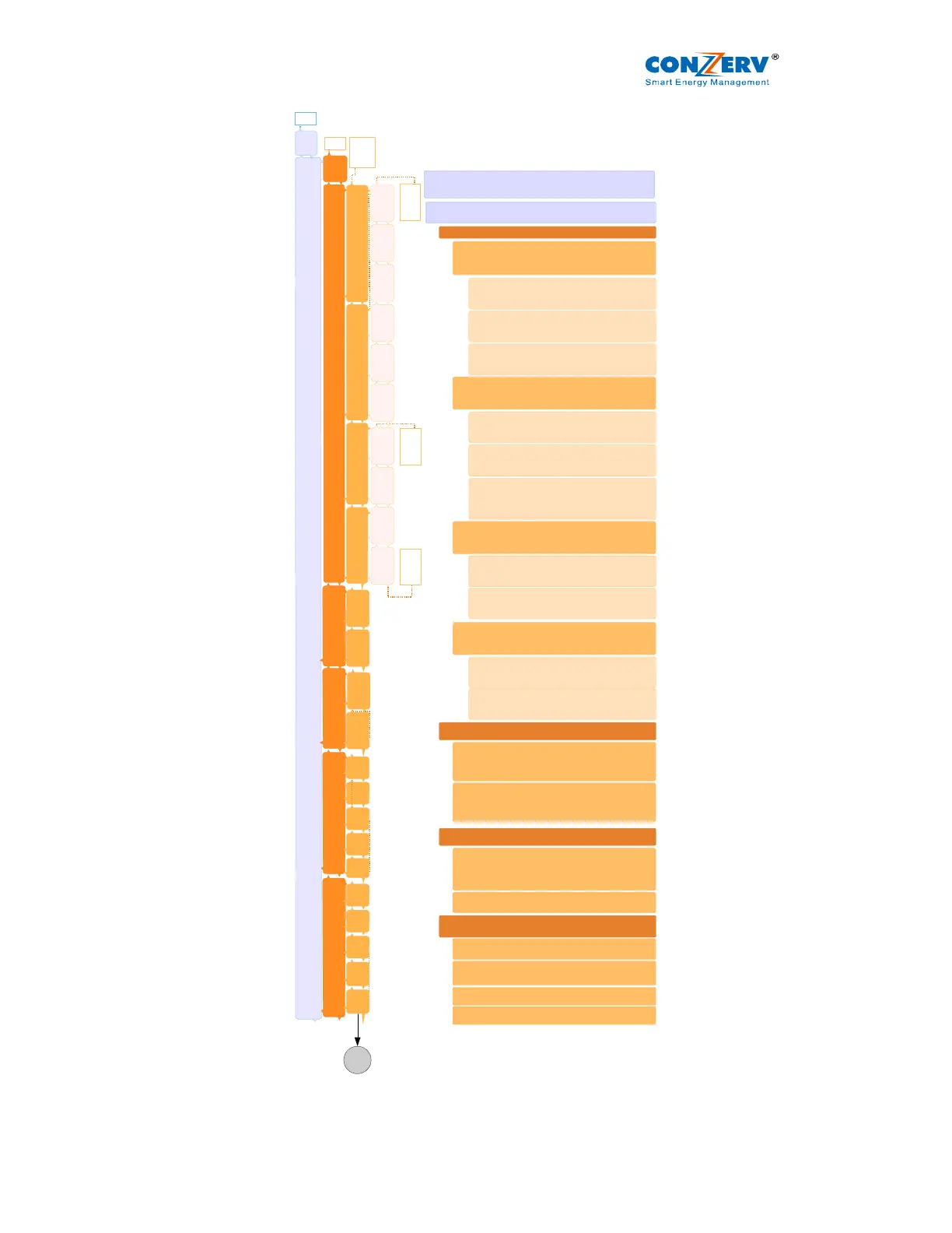
Figure 3.1: The Display Flow Chart EM 6400, EM 6434 and EM 6459 v03.02
INTG
Wh
PROG
V 12
23
31
RUN
V LN
A
F
SET
RMS V LL
A
PF
PF1
2
3
V 1
2
3
A 1
2
3
L% 1
2
3
A
0
1
2
3
UNB
RPM
F
VA1
2
3
W 1
2
3
VAR1
2
3
PF1
2
3
V12
23
31
PF1
2
3
VA
W
VAR
W
VAR
PF
THD
V
0
0
1
2
3
A
0
0
1
2
3
DM
VAd
Rd
TR
MD
HR
VAh
VARh
-VARh
Run.h
R.Wh
REV
R.VAh
R.VAR
-R.VAR
R.run
DIAG
W
VAR
PF
CLR
V12 = RMS voltage phase1-2
V23 = RMS voltage phase 2-3
V31 = RMS voltage phase 3-1
RUN = This menu has all the display pages. You can scroll
through the display pages using the front panel keys
A
0
1 = Current phase angle of phase 1 in degrees
A
0
2 = Current phase angle of phase 2 in degrees
A
0
3 = Current phase angle of phase 3 in degrees
SET= This menu has the entire PROG menu. The user
programmable parameters are listed here
RMS = RMS value display pages are in sub level
VLL = Phase – Phase voltage average
A = Current average
PF = Power Factor average
VLN = Phase – Neutral voltage average
A = Current average
F = Frequency in Hz
V1 = RMS voltage phase1-neutral
V2 = RMS voltage phase2-neutral
V3 = RMS voltage phase3-neutral
A1 = RMS current phase1
A2 = RMS current phase 2
A3 = RMS current phase 3
L1% = % of load phase 1
L2% = % of load phase 2
L3% = % of load phase 3
UNB = % of unbalanced load
RPM = Source RPM . Poles programmed in PROG
Menu
F = Frequency in Hertz
VA = Volt – amperes total
W = Watts total
VAR = VAR total
VA1 = Volt – amperes, phase 1
VA2 = Volt – amperes, phase 2
VA3 = Volt – amperes, phase 3
W1 = Watts, phase 1
W2 = Watts, phase 2
W3 = Watts, phase 3
VAR1 = VAR, phase 1
VAR2 = VAR, phase 2
VAR3 = VAR, phase 3
W = Watts total
VAR = VAR total
PF = PF total
PF1 = Power factor, phase 1
PF2 = Power factor, phase 2
PF3 = Power factor, phase 3
THD = Total Harmonic Distortion
V
0
0
1 = Voltage THD, phase 1
V
0
0
2 = Voltage THD, phase 2
V
0
0
3 = Voltage THD, phase 3
A
0
0
1 = Current THD, phase 1
A
0
0
2 = Current THD, phase 2
A
0
0
3 = Current THD, phase 3
DM = Demand
VAd = VA demand (Wd = W demand selectable
through PROG Menu)
Rd = Rising demand
TR = Time remaining
MD = Maximum demand
INTG = Integrator, accumulated readings are displayed
in sub level
VAh = Volt-ampere hours
Wh = Watt hours. If watts is -ve, Vah, VARh, Wh,
-VARh do not integrate
VARh = VAR hours, inductive
-VARh = -ve VAR hours, capacitive
1
 Loading...