38
Appendix...
GB
IE
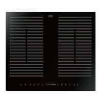
CLIND2BK-C Induction Hob
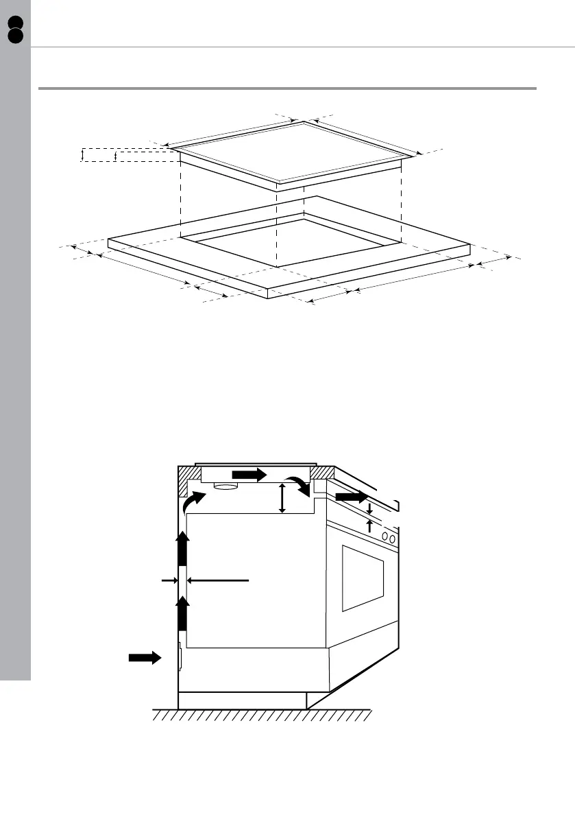
Positioning
590mm
520
m
m
56
0
mm
50
m
m
5
0
m
m
49
0mm
5
0mm
5
0mm
56mm
60mm
• Cut out the work surface according to the sizes shown in the drawing.
• For the purpose of installation and use, preserve a minimum of 50 mm space
around the hole.
• Be sure the thickness of the work surface is at least 30 mm. Select heat-
resistant work surface material to avoid larger deformation caused by the
heat radiation from the hotplate.
Air intake
Air exit
Min. 5 mm
Min. 20 mm
Min. 50 mm
• The induction hob must be well ventilated and the air inlet and outlet at the
bottom of the appliance must not be blocked. The fan situated at the bottom
of the hob must have sufcient space and ow of fresh air at all times.
Installation
 Loading...