496478 25
3. Installation
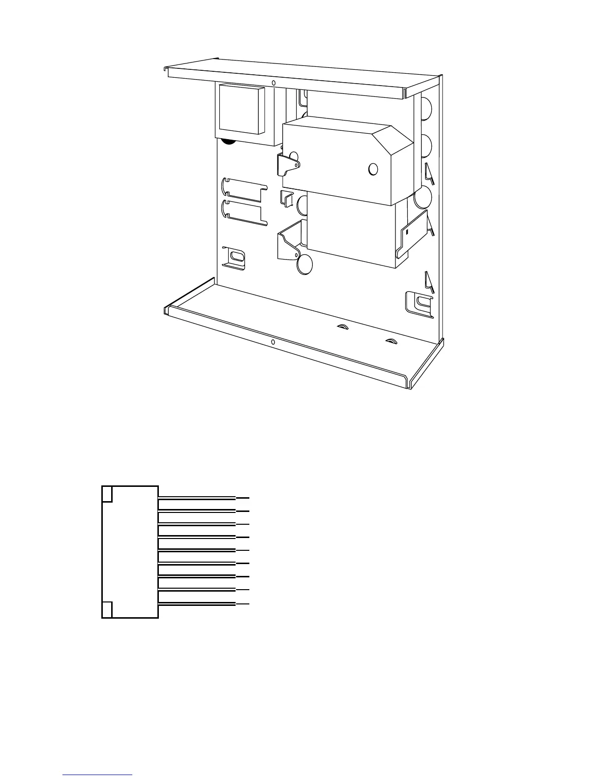
Figure 18. Fitting a Plug ByCommunicator
4. Make any necessary connections from the communicator to the Comms
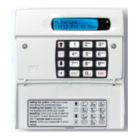
Wiring Harness. Figure 19 shows the outputs available on the free ends
of the Comms Wiring Harness.
1 (Brown) Fire. -ve applied (+ve removed) in alarm
2 (Orange) PA. -ve applied (+ve removed) in alarm
3 (Yellow) Burg. -ve applied (+ve removed) in alarm
4 (Green) Open/Close. -ve applied (+ve removed) in alarm
5 (Blue) Alarm abort. -ve applied (+ve removed) in alarm
6 (Purple) Line Fail Input. +12V applied to indicate telephone line fail
7 (White) Tell Back Input +12V applied to change from engineer to customer reset
8 (Black) 0V
9 (Red) 12V
Figure 19. Communications Wiring Harness.
5. Plug the Comms Wiring Harness onto the communications connector on
the main PCB (see Figure 4).
6. Re-fit the PCB to the support pillars.