Do you have a question about the Cooper DF6000 and is the answer not in the manual?
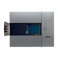
Provides an overview of the DF6000 system and its capabilities.
Outlines a typical program and timetable for a DF6000 installation project.
Details standards and best practices for designing DF6000 systems.
Lists and describes the various equipment compatible with the DF6000 system.
Describes the different types of analogue addressable detectors for the DF6000 system.
Details the range of purpose-designed callpoints for the DF6000 system.
Describes the available loop-powered sounders and beacons for the DF6000 system.
Details standalone sounders, including weatherproof versions.
Describes loop-powered beacons for visual alarm indication.
Details base sounders with integrated beacons for combined alarms.
Details base beacons for visual alarm indication without sound.
Explains interfaces for integrating other systems with the DF6000.
Describes a 3-channel input/output device for monitoring and control.
Details a 1-channel input/output unit with high-capacity switching.
Describes a unit for connecting conventional detectors to the DF6000 loop.
Details an interface for conventional detectors and sounders in specific zones.
Explains the spur isolator for loop configuration and fault tolerance.
Describes a controller for up to four conventional sounder circuits.
Introduces a range of compact interface modules for various functions.
A competitively priced input module for accepting external signals.
A competitively priced output module for controlling external devices.
A compact single zone input interface with integral isolators.
A micro input module used as a callpoint for external signals.
A micro output unit identified as a sounder output.
A micro output module for controlling equipment requiring power removal for reset.
A micro input unit for non-fire applications.
Interfaces for controlling and displaying the status of AHU fans.
Details compatibility requirements for detectors, callpoints, and sounders.
Specifies compatible detector types for the DF6000 system.
Specifies compatible callpoint types for the DF6000 system.
Specifies compatible sounder types and requirements for the DF6000 system.
Discusses adding additional relays and compatibility constraints.
Provides guidelines for EMC compliance during installation.
Provides a general overview of the DF6000 system's features and operation.
Describes the touch screen display and its user interface features.
Explains on-site system configuration and maintenance capabilities.
Details the advanced capabilities for programming sounder patterns and responses.
Explains the intelligent soft addressing technology for loop configuration.
Describes the system's design for easy future expansion and device addition/removal.
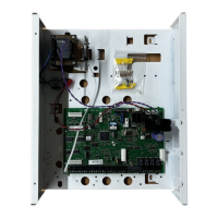
Highlights the integrated power supply and battery for simplified installation.
Details the availability and functionality of an optional integral printer.
Describes the optional lockable cover for enhanced security and access control.
Provides detailed technical specifications for power supply, batteries, and inputs.
Technical details related to the mains power supply for the DF6000.
Technical specifications for the system's batteries.
Technical details regarding system inputs, including addressable loops.
Details the various output capabilities and specifications of the DF6000 system.
Specifications for conventional sounder circuits.
Details the output for fire protection equipment.
Details the output for fault routing equipment.
Information on auxiliary relays and their capabilities.
Details the auxiliary 24V DC output.
Information on the mimic output for displays or repeater panels.
Lists and explains optional functions that comply with EN54 standards.
Specifics on panel sounder outputs and requirements.
Details output for fire alarm routing equipment.
Details output for fire alarm protecting equipment.
Details output for fault warning routing equipment.
Explains configurable delays for system outputs.
Describes dependencies for alarm signals based on multiple zones.
Explains the function of the alarm counter.
Details an optional auxiliary board requirement.
Describes inputs and outputs for communication with a fire brigade panel.
Lists and describes the specific outputs for the fire brigade panel interface.
Lists and describes the specific inputs for the fire brigade panel interface.
Electrical characteristics for the German interface.
Input characteristics for the German interface.
Details on monitored inputs for the German interface.
Details on relay outputs for the German interface.
Details on general outputs for the German interface.
Lists optional functions not covered by EN54 standards.
Describes the Italian mode with specific fire detection delays.
Describes the Swedish mode and access level requirements.
Allows auto-learning of one loop at a time.
Explains the alarm verification feature with a delay.
Describes timer functions T1 and T2 for alarm delays.
Describes timer functions with callpoint override capability.
Covers allowable cable types and wiring requirements for loop connections.
Provides typical resistance values for FP200 cable.
Details methods for fixing mains cables securely.
Provides general guidelines and precautions for installing the panel.
Specific instructions and warnings for the installation process.
Information on panel mounting, backbox dimensions, and cabling installation.
Instructions for flush and surface mounting the backbox.
Steps for installing power and loop cables after mounting the backbox.
Details on how to connect the mains supply to the system.
Application of mains connection rules to distributed power supplies.
Requirement to segregate fire alarm cables from other wiring.
Describes methods for taking spurs off the loop.
Explains how to network DF6000 panels together to form a system.
Details the panel's input and output terminals and their functions.
Describes the function of panel inputs, like class change.
Describes the function of panel outputs, like sounders.
Details the output for fire protection equipment activation.
Details the output for fault warning routing equipment.
Information on the auxiliary relay output.
Details the auxiliary 24V DC output.
Information on the mimic output for external displays.
Covers routine maintenance procedures for the DF6000 system.
Daily checks to ensure the system is operating correctly.
Procedures for performing weekly system tests.
Quarterly checks including log review and battery inspection.
Annual testing procedures for sensors and callpoints.
Recommendation for smoke detector cleaning every 2-3 years.
Recommendation for replacing the sealed lead-acid battery every 5 years.
Instructions for cleaning the panel.
Information for ordering replacement printer paper.
Instructions on how to attach the panel door correctly.
Details on fitting an optional hinged cover for the panel.
Steps for loading and fitting the printer paper roll.
Explains the walk test mode for efficient system testing.
Covers system configuration options and PC software usage.
Facility to test and set system sounders with minimal disturbance.
Function to visually inspect detector communication status.
Describes downloading configuration data to DF6000 panels using PC software.
Provides guidance on identifying and resolving panel faults using voltage readings.
Explains the communication protocols used by the DF6000 system.
Details the use of PC software for system commissioning and configuration.
Explains how to program device inputs for fire, fault, reset, etc.
Allows defining zones or addresses to be isolated upon device activation.
Describes configuration options for device outputs, including delays.
Allows delaying device output activation by a user-defined value.
Enables manual intervention to override output delays from callpoints.
Details panel output configurations, including dependency types.
Assigns zones to panel outputs based on fire conditions or coincidences.
Identifies and explains the system LEDs and physical controls on the panel.
Explains the function of each system status LED on the panel.
Describes the purpose of zonal LEDs for indicating fire status.
Identifies the touch screen display as a primary interface.
Identifies the door for accessing the printer compartment.
Identifies the location for an optional printer.
Lists and explains specific controls like log book storage and supervisor key access.
Location for storing the system log book.
Specifies the location for inserting the supervisor access key.
Identifies the location of the printer unit.
Location for storing printer paper rolls.
Identifies the optional hinged cover.
Button for navigating upwards through menus or lists.
Button to silence audible alerts.
Button for navigating downwards through menus or lists.
Detailed description of the touch screen's functionality and display features.
Explains how to operate the panel using the touch screen interface.
Describes the functions accessible at public access level without a passcode.
Explains how to activate the building evacuation procedure at access level 2.
Details the procedure for silencing active alarms.
Explains how to mute the panel's buzzer.
Describes the process of resetting the panel.
Explains the indication and meaning of pre-alarm events.
Shows how to view and manage disabled devices within the system.
Explains how to access and view system faults.
Details the process of enabling or disabling system components via the 'Others' menu.
Explains how to print various system logs and information.
Describes how to perform a lamp test for all panel indicators.
Details the procedure for conducting a weekly system test.
Explains how to access and view the system's event log.
Describes the function to scan and verify loop configuration.
Explains how to replace an existing device with a new one without losing programming.
Details how to test individual devices at access level 3.
Explains how to put specific zones into test mode.
Describes the mode for testing sounder levels and patterns.
Function to enable or disable global flashing of device LEDs.
Explains the procedure for performing a one-person walk test of devices.
Procedure for loading configuration data from a laptop to the panel.
Procedure for downloading configuration data from the panel to a laptop.
Steps for initiating the auto-learn process to configure the system.
Describes how to erase the system's event log.
Provides access to detailed system information, including loop and device counts.
Allows viewing and checking analogue levels of connected devices.
Covers configuration options for the printer.
Allows changing the unique number assigned to each panel in a network.
Configuration for setting the total number of panels in a networked system.
Options for enabling or disabling the screen cover feature.
Access point for programming input/output modules and sounder settings.
Allows configuring global sounder volumes and tones.
Procedure for setting the panel's date and time.
Allows editing the text descriptions for specific device addresses.
Allows editing the text descriptions for specific zones.
Allows editing the text description for the panel itself.
Allows assigning devices to specific zones or reconfiguring zone assignments.
Details how to change the user access passcode for the panel.
Procedure for adding a new zone to the system configuration.
Procedure for deleting an existing zone from the system.
Steps for adding a new device to a specific loop and scanning for it.
Procedure for removing a device from the system configuration.
Allows setting the class (e.g., A1R, BS, CS) for heat detectors.
Configuration options for network messaging and communication between panels.
Explains the system's password protection features and default codes.
Details the installation and connections for the Spur Isolator.
Details the installation and connections for the 4 Way Sounder Controller.
Details the installation and connections for the Zone Monitor Unit.
Details the installation and connections for the Shop Monitor Unit.
Details the installation and connections for the 1 Way Input/Output Unit.
Provides wiring diagrams for the Detector Base.
Illustrates a typical system wiring diagram connecting various components.
Details the installation and connections for weatherproof wall sounders.
Details the installation and connections for internal wall sounders.
Provides specifications and wiring for the Base Sounder.
Details the installation and connections for the 3 Way Input/Output Unit.
Details the installation and connections for the Loop Powered Beacon.
Details the standard connections for Callpoints.
Shows the location and details of EN54 specification labels.
Provides guidance on the safe disposal of used batteries.
Displays CE marking and compliance information for the DF6000 system.
| Brand | Cooper |
|---|---|
| Model | DF6000 |
| Category | Control Panel |
| Language | English |