12
Before commencing electrical installation and wiring, carefully read the following notes:
• Power must be supplied by a safety isolation transformer (Class 2) or DC power supply with no
Earth Ground connection on the low voltage side (24VAC or 24 VDC)
• The cable for the relays must be sized and fitted with fuses based on the rated voltages, currents,
and environmental conditions.
• If stranded wires are used, it is recommended to use an end terminal.
• To comply with RFI immunity regulations, the Modbus communication cable shield at the super-
visor controller (E2, E3, Site Supervisor) end of network must be connected to Earth Ground (for
example, to the earthed chassis, earth bar, etc.)
• Complete all wiring before powering on.
• Secure the detector cover with the four screws.
• Power the device on and set the parameters if the settings were not
previously made using the rotary switch.
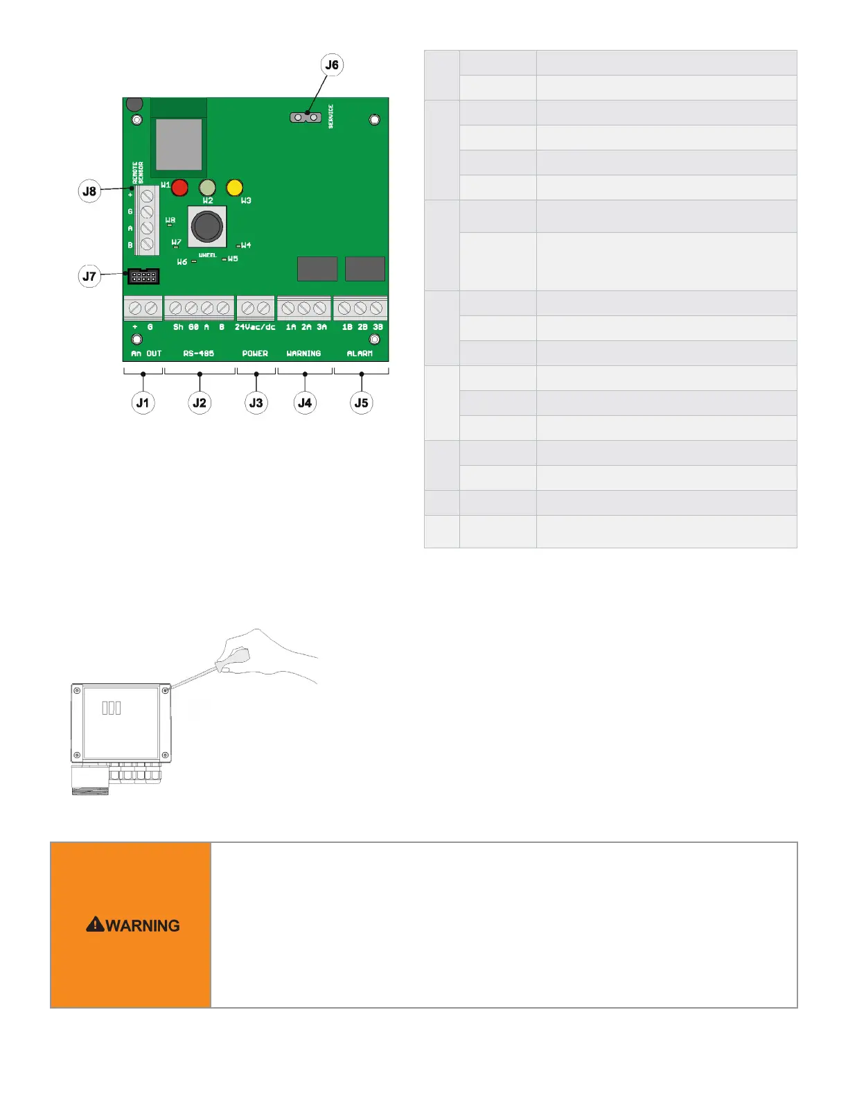
J1
+ Analog output
G Analog output reference
J2
Sh Shielded RS485 cable
G0 GND for RS485
A Tx + / Rx + for RS485
B Tx- / Rx- for RS485
J3
+24 Vac/DC
For Vac power supply, connect the second
transformer wire
+24 Vac/DC
For Vdc power supply, connect one of the two
power wires, the device automatically recognizes
whether this is + or GND. For AC power supply,
connect one of the two transformer wires.
J4
1A NO contact for the warning/fault relay
2A Common for the warning/fault relay
3A NC contact for the warning/fault relay
J5
1B NO contact for the alarm relay
2B Common for the alarm relay
3B NC contact for the alarm relay
J6
+ NC contact for the alarm relay
G Service voltage reference
J7 / Built-in version sensor connector
J8 /
Remote version sensor connector (connection not
to be used for built-in products)
All external circuits connected to device shall be
double or reinforced isolated from mains meet SELV
and Limited energy requirements according to clause
9.4 of UL61010-1 3rd edition.
Electrical Connection
Connection Table
 Loading...