14
5.3 Device Setup Using Rotary Switch
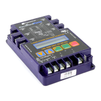
The Rotary Switch (R1) is located on the electronic board of the device.
OFF
LOW INTENSITY ON
HIGH INTENSITY ON
LOW INTENSITY BLINK
1 2 3 4 5 2-5 6
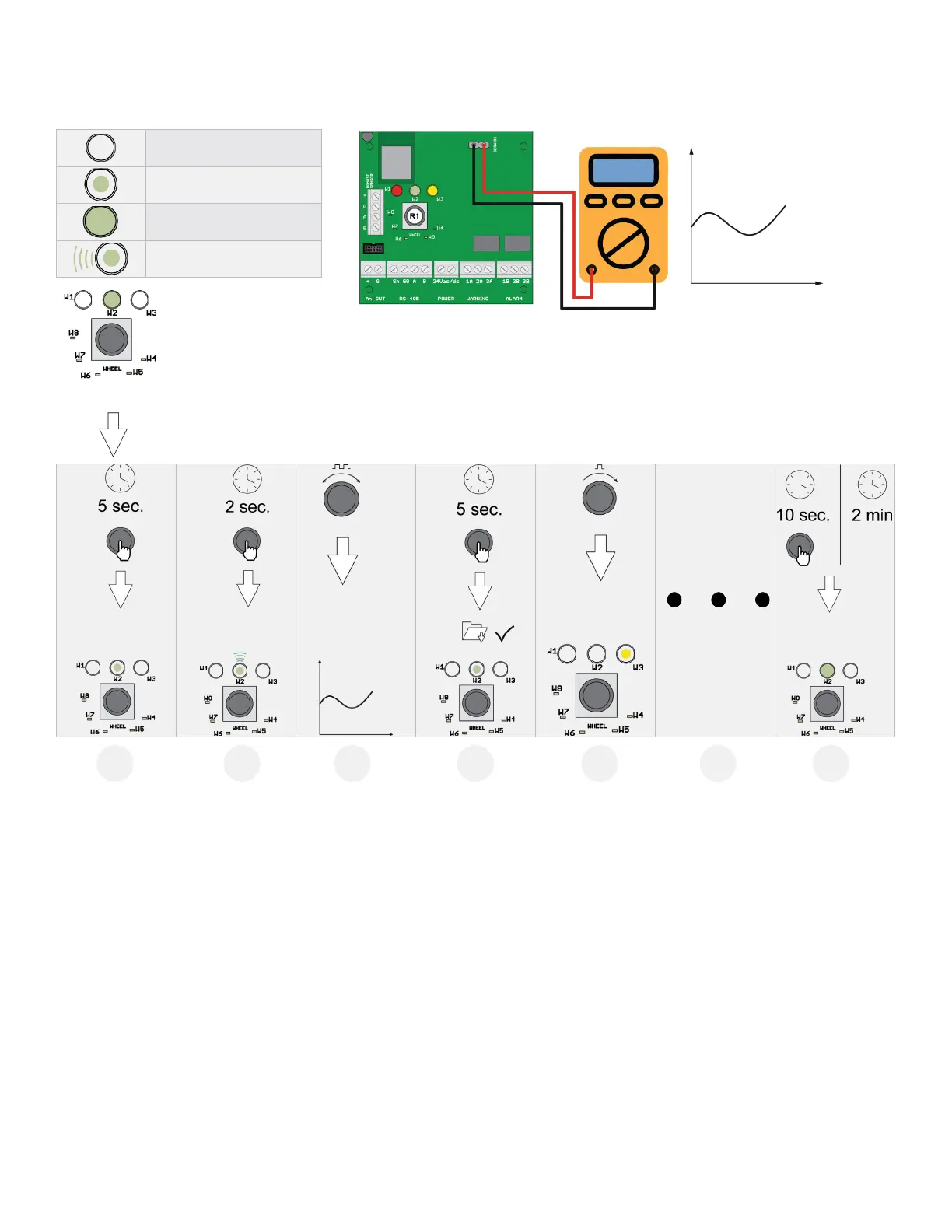
The basic configuration can be performed using the rotary switch, following the instructions described below. To
complete the configuration, a digital multimeter is required, with the test leads connected to connector J6. In this way,
the tester will show a voltage between 0 and 10 Volts, indicating the value selected by the rotary switch. The meaning of
the voltage value displayed changes depending on the selected function the table below shows the meaning of each
voltage for each function.
Setting mode is activated by pressing and holding the rotary switch for 5 seconds. The LED that is ON acts as the menu
point, indicating which parameters will be set (all the other LEDs are OFF). Turn the switch to select the parameter to be
set. Reading the table, the voltage read with a voltmeter connected to the service terminal indicates the chosen setting.
Pressing the rotary switch for 2 seconds accesses the selected parameter. The corresponding LED flashes. Turning the
rotary switch changes the parameter setting.
After having made the setting, pressing the rotary switch for 5 seconds saves the new value. Turning the rotary switch
again moves to the next parameter.
After two minutes of inactivity or pressing the rotary switch for 10 seconds, the detector returns to normal operating
mode.
 Loading...