25
5.8 Modbus Network
For the Modbus RS485 network, use a shielded 3-wire cable. Recommended Belden 3106A (or equivalent).
The Modbus communication parameters can only be set using the Copeland CRLDS Application or the rotary switch on
the device’s electronic board.
Make sure that the network communication parameters are configured in the same way, including on the controller. To
ensure optimal operation of the serial network, observe the following guidelines:
• Make sure that the devices are configured with a single bus layout. Connecting several buses in parallel or branching several
devices from the main bus may introduce incorrect combinations of signal impedance, reflections and/or distortions.
• Avoid using excessively long connections when connecting devices to the serial bus. The device - bus connection must not
exceed a maximum length of 100 meters.
• Make sure that the polarity of the A / B signal is maintained across the serial network.
• Earth the cable shield only on the main unit side.
• Connect the cable shield to terminal SH on the gas detector.
• Make sure that the shield is intact across the serial network.
• Do not use the shield connection as a signal reference. Use a cable that provides a dedicated wire for the signal reference.
• Connect the signal reference to terminal GND on the gas detector.
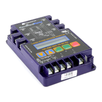
The CRLDS-1000 and CRLDS-CO2 detectors feature a Modbus RTU digital interface. All of the status messages and most
of the parameters accessible and/or configurable via the Bluetooth® interface are also accessible and/or configurable via
MODBUS controller.
Parameter for RS485 Communication selectable via app or rotary switch
Parameter Possible values Default value
Address 0 to 247 via app
0 to 100 via device
0
Baud rate 9600 or 19200 19200
Stop bits 1 or 2 2
Parity None, Even or Odd None
The password to unlock the device is 2222.
 Loading...