300 SERIES USER GUIDE
3
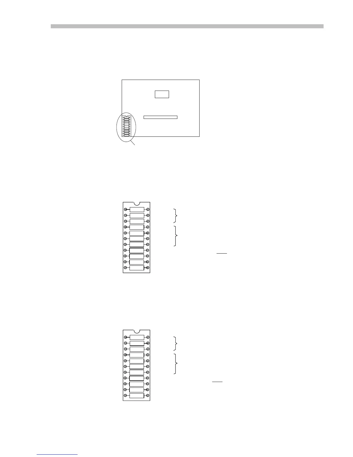
J17 Component Header
This is an 11-position socket which holds resistors and capacitors which are used for
tachometer scaling and compensation, amplifier compensation, and current limiting.
Location
Current-Mode Setup (Standard configuration)
This is the standard configuration as delivered from the factory. In this mode, a voltage
at the reference inputs will force a current at the amplifier outputs. This is also called the
flat-gain mode because it provides the maximum bandwidth which remains constant over
the 3 kHz range.
Velocity Mode Setup (Use components supplied)
Use the components supplied in the brown bag to replace R5,R7, and C6. This will setup
the amplifier for use with tachometers. See Mode Setting for further details.
4-PIN
22-PIN
J17 HEADER
AMPLIFIER WITHOUT MB4 CARD
1
2
3
4
5
6
7
8
9
10
11
22
21
20
19
18
17
16
15
14
13
12
R1
R2
C3
C4
R5
C6
R7
R8
JP9
R10
R11
10 K
Value
Component
40.2 K
OPEN
330 pF
46.4 K
.01 uF
JUMPER
10 K
JUMPER
49.9 K
49.9 K
Current Limit ; 10K = 100% of peak rated current
Enable polarity ; IN = Enable, OUT = Enable
Aux Input Gain
Ref Gain ; amplifier gain = Ipeak/10V
Function as Shown
Notes:1. R1, R2, C3 and C6 have no function in current mode.
2. Current-limiting is non-linear with respect to R8. For best results, substitute 10K pot
for R8, adjust for desired current-limit, and replace with fixed resistor.
Not used in current-mode
Flat gain
1
2
3
4
5
6
7
8
9
10
11
22
21
20
19
18
17
16
15
14
13
12
R1
R2
C3
C4
R5
C6
R7
R8
JP9
R10
R11
10 K
Value
Component
40.2 K
OPEN
330 pF
499 K
.01 uF
10 MEG
10 K
JUMPER
49.9 K
49.9 K
Tach scaling ; 10V @ Ref = 8V @ Tach
Compensation (see Mode Setting section, p. 23)
Current Limit ; 10K = 100% of peak rated current
Enable polarity ; IN = Enable, OUT = Enable
Aux Input
Ref Gain ; servo preamp DC gain = 210
Function as Shown
Notes:
1. R1, R2, and R11 interract to affect tachometer scaling and servo preamp gain.
2. Current-limiting is non-linear with respect to R8. For best results, substitute 10K pot
for R8, adjust for desired current-limit, and replace with fixed resistor.
(see Note 1 and Tachometer Scaling, p. 25)
 Loading...