300 SERIES USER GUIDE
13
Power Supply Considerations
1. Determine the maximum voltage required to drive your motor or load at peak current and peak RPM (in
the case of a motor).
Add extra for losses in the amplifier (see p. 10, Output Voltage Swing).
Add an extra 5-10% for power supply ripple.
Use this value, and the amplifier's continuous current rating as your nominal power supply specification
at normal line voltage.
300 series peak currents of 2-2.5X the continuous current rating can usually be tolerated by off-the-shelf
transformer-rectifier-capacitor power supplies.
(See appendix for a complete listing of standard power supplies)
2. Where the amplifier is to be mounted more than 18" away from the power supply filter capacitor, install
a 200uF. (minimum) filter capacitor across the amplifier +HV and Gnd terminals as a local bypass
capacitor. The voltage rating of this capacitor should be compatible with your supply voltage.
3. Use the current monitor output to check for clipping when your system is up and running. This could be
an indication that there is insufficient buss voltage to drive the commanded current through the load.
4. When operating at lower supply voltages, such as 24V or less, check the Normal LED. If it goes out
occasionally, this could mean that the buss voltage 'sag' during periods of high current demand, and is
lowering the buss voltage below the under voltage cutoff point (<16V). If this occurs, consider using a
larger filter capacitor, or raising the supply voltage.
5. If the load has a high inertia, you may need a regenerative energy dissipator, or larger filter capacitors.
Whe a heavy load is decelerated, the amplifier will transfer energy from the motor to the power supply.
This will 'pump-up' the buss voltage, and can cause either an overvoltage shutdown, or damage the
amplifier.
6. If you see the Normal LED go out when the load is decelerated, it is a sign that the buss is "pumping-
up", and you will have to take measures as suggested above, lower the buss voltage, or decelerate the
load more slowly.
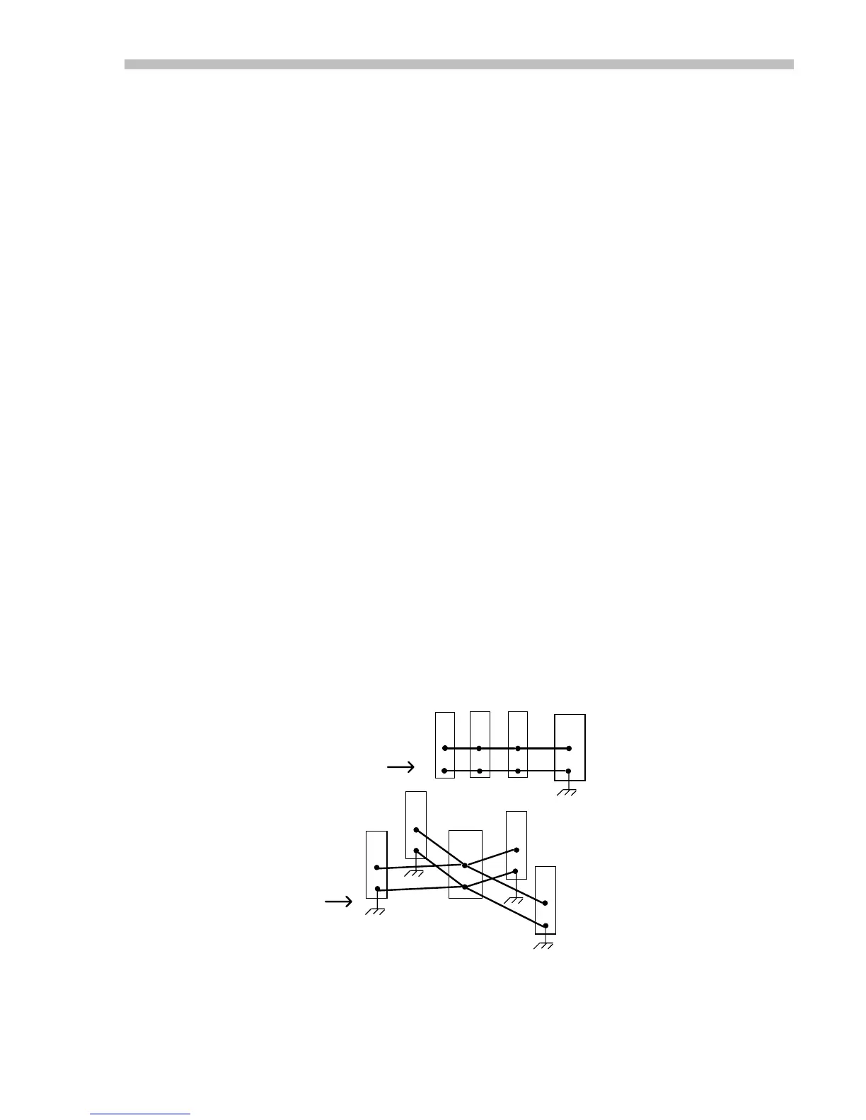
7. When multiple amplifiers are connected to the same power supply, use a 'star' wiring configuration.
Don't 'daisy-chain' amplifiers by connecting one to the next, and so on. Make connections between each
individual amplifier and the power supply, and ground each amplifier at pin DD (P1-4 on the MB4 card)
leaving the (-) terminal of the filter capacitor disconnected from ground. Doing this will keep the
reference and logic inputs of the amplifiers referenced to ground, while the voltage at the negative
terminal of the filter capacitor changes in response to the current drawn through the amplifier wiring.
8. Regulated power supplies frequently do not have adequate output filter capacity to power a servo
amplifier. They can go into over-current foldback during periods of high output currents. If using such
supplies, it may be necessary to add an external filter capacitor (4-5000 uF).
Multiple Amplifier Power Connections
AA
DD
AA
DD
AA
DD
AA
DD
DON'T
AA
DD
AA
DD
AA
DD
+
-
+
DO THIS
DO
THIS
POWER
SUPPLY
POWER
SUPPLY
-
Fig. 7
 Loading...