300 SERIES USER GUIDE
10
Amplifier with MB4 Mounting Card
: Current-Mode,
WITH Tachometer
Use this checklist for applications that do employ a tachometer. These include
microprocessor control systems that get position feedback from an encoder on the
motor, as well as non-motor applications such as magnet-coil, solenoids, or other loads
that require a set current from the amplifier in response to a control-voltage at the
inputs. The components on the J17 header come from the factory preset for this
operating mode. See functional diagram on page 2.
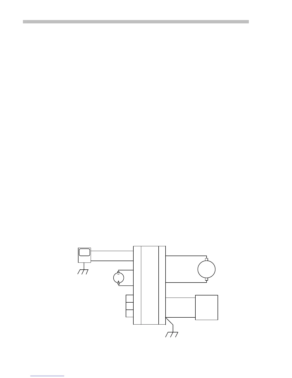
1. Connect DC power supply to MB4 card P1 (see diagram below). Check voltage to
see that is is within the amplifiers' rating.
2. Ground amplifier to chassis at pin P1-4.
3. Connect motor or load between OUT+ and OUT-. Do not ground load!
4. Connect reference voltage source to REF+ and REF- inputs.
5. Ground ENABLE,POS ENABLE, NEG ENABLE to amplifier logic ground.
6. Set REF GAIN pot to full CW.
7. Set FEEDBACK pot to full CW.
8. Set CURRENT LIMIT pot to full CW.
9. Set V
ref
to 0V
10. Turn power on
11. Check for green LED indicating Normal operation.
12. Adjust BALANCE trimpot for 0.0V between OUT+ and OUT-
13. Momentarily increase Reference voltage (±10V max).
14. Check motor direction: is it OK?
YES: continue
NO: remove power, reverse connections to Ref+ and Ref-.
15. Set Reference voltage to maximum value (+/-10V)
16. Check load current at CURRENT MONITOR output
17. Apply step or square-wave signal to Ref-inputs, adjust FEEDBACK CCW for best
response with no oscillation.
Amplifier Connections
Numbered terminals are on the brown 15-pin connector. Double-letter terminals are on
the orange 4-pin connector. See appendix for connector part numbers.
3
2
1
11
+HV
GND
+
-
DC
OUT+
OUT-
MOTOR
1
4
CHASSIS GND
8
15
2
3
REF+
REF-
ENABLE
POS ENABLE
NEG ENABLE
LOGIC GND
CONTROLLER
OUT
GND
POWER
SUPPLY
P2
P1
MB4 Card
6
14
TACH
Fig. 4
 Loading...