300 SERIES USER GUIDE
17
DC Power Outputs
All internal supply voltages are derived from the high-voltage supply. These internal voltages are
available at the signal connector for certain user applications. All are current-limited by
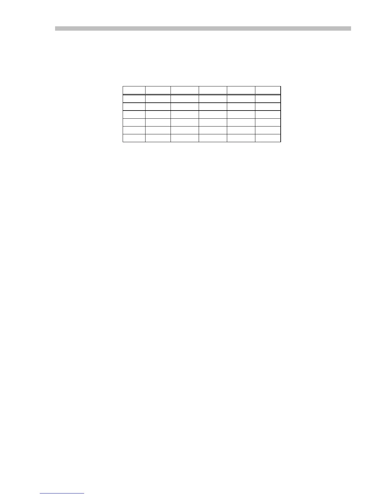
series resistors (Rser) and are intended for low-power applications. Table 8 lists the
connector pin, voltage, and series resistance for each of these outputs:
Vout Std MB4 Eur Rser Iout
22 pin P2 DIN
+5
20 n/a n/a 2.49 K 100 uA
+11
6 n/a n/a 20 K 50 uA
-11
8 n/a n/a 20 K 50 uA
+14
18 5 C8 1 K 3 mA
-14
n/a 13 A8 None 1 mA
Table 8
Std ; Standard amplifier without MB4 card. Pin numbers refer to 22 pin connector.
MB4 ; Amplifier + MB4 card combination. Pin numbers refer to MB4 15 pin connector P2.
Eur ; Amplifier + EC2 Eurocard combination. Pin numbers refer to Eurocard DIN connector
P2.
Rser ; Internal resistance in series with voltage source shown.
Iout ; Permissible current to external loads.
 Loading...