300 SERIES USER GUIDE
19
MB4 Mounting Card
The MB4 card adds features and options to the 300 series amplifiers that are not
available on the basic unit. These include PWM inputs, voltage-mode amplification, IR
compensation, and output 'edge' filters.
The MB4 card connects to the amplifier via connectors J3 & J4. The user makes
connections to the amplifier/card assembly via connectors P1 (motor, and high voltage
DC supply) , and P2 (reference, tach, and aux inputs, and Enable signals).
Notes on Nomenclature
I,O,P ; Inputs TO MB4 Card, and Outputs FROM MB4 Card, P = Passive
P1 ; Motor & DC Power connections to the MB4
P2 ; Signal connections to the MB4
J3 ; Motor & Power connections between the amplifier & MB4 card
J4 ; Signal connections between the amplifier & MB4 card
N.C. ; No Connection
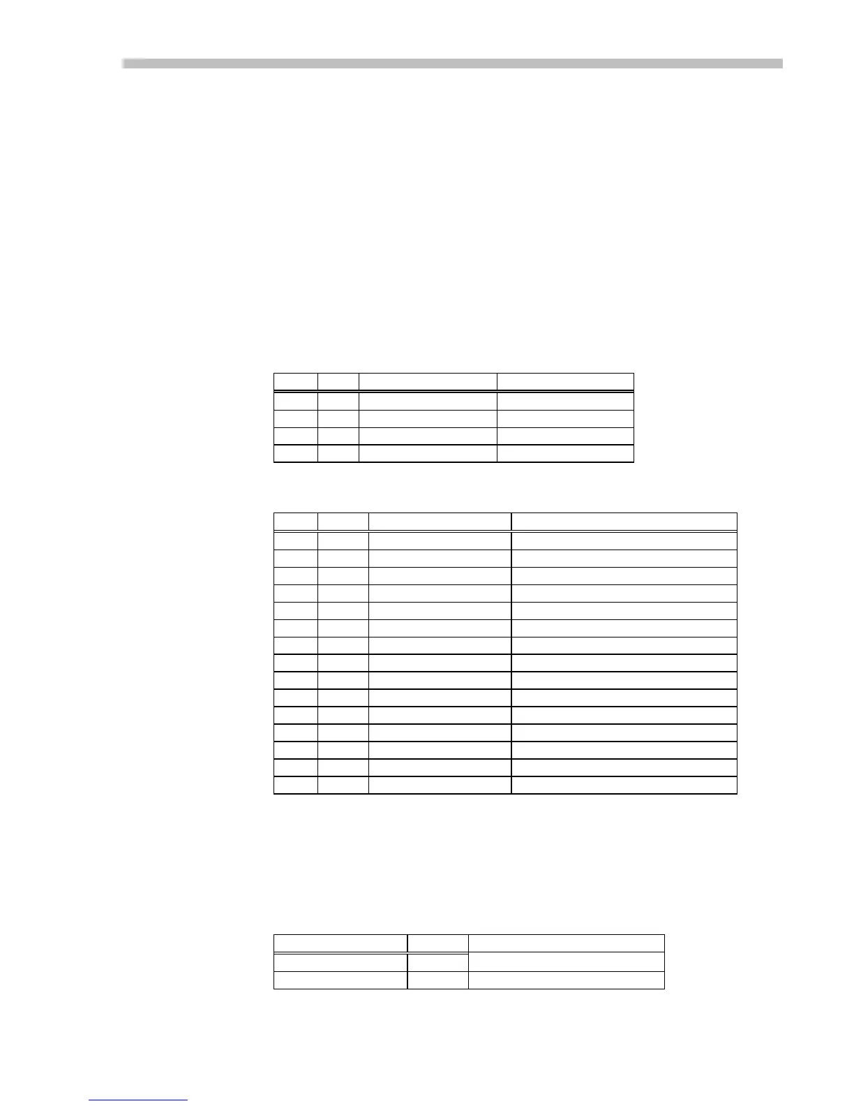
P1: 4 Pin power connector
P1 J3 Signal Name Function
1 AA High Voltage Power input to card
2 BB Neg Output Amplifier output (-)
3 CC Pos Output Amplifier output (+)
4 DD Power Ground Power return
Table 11
P2: 15 Pin signal connector
Pin Type Signal Remarks
1 I /Neg Enable GND Enables, open-circuit Disables
2 I /Pos Enable GND Enables, open-circuit Disables
3 I /Enable GND Enables, open-circuit Disables
4 O Normal HI when Normal, LO if fault
5 O +14V output 14V in series with 1K ohms
6 I Tach Tachometer voltage input
7 I Aux Single-ended control voltage input
8 I +Ref Input Analog input voltage (+) terminal
9 I PWM Pulse Input (Only with -D option)
10 I /Reset GND momentarily to reset fault
11 P Ground Use for Enable signals
12 I PWM Direction Input (Only with -D option)
13 O -14V Output (with -V option only)
14 P Ground Tacho return input or signal ground
15 I -Ref Input Analog input voltage (-) terminal
Table 12
Status Output
The Normal output signal from the amplifier can be routed directly through the MB4
card to this output pin, or can drive an open-drain MOSFET that will be OFF during
normal operation, and turn ON during a fault condition. In this way several amplifiers
can be 'wire-ORed' together to a 'system-OK' line that will be normally HI, and go LO if
any amplifier goes into a fault condition.
Output type JP-104 Rating
MOSFET output 1-2 50V, 100mA Table 13
Amplifier Normal 2-3 HCMOS in series with 1.87K
Amplifier Signal Connector (J4)
These are the connections between the amplifier and the MB4 card.
 Loading...