300 SERIES USER GUIDE
21
MB4 Card Jumper Settings
Table 15 shows the settings of the on-card jumpers for the various card and setup
options. Jumpers consist of two-pin shorting connectors on three-pin p.c. board headers.
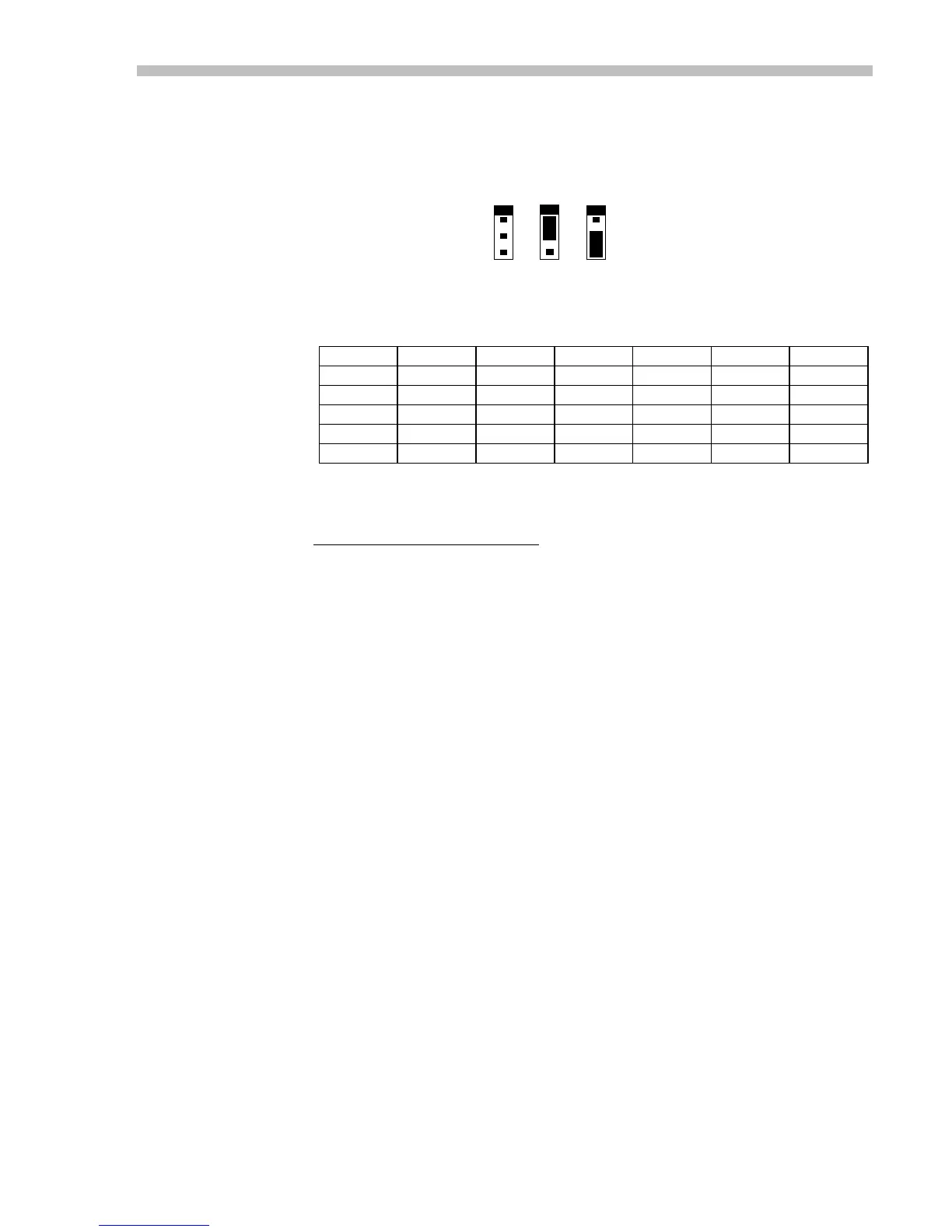
The shorting connector can connect pins 1-2, or 2-3, as shown below.
Amplifier Mode Input Type
Curr Volt IR Comp Analog PWM PWM
0-100% 50%
JP02
1-2 2-3
JP182
2-3 1-2 1-2
JP72
2-3 1-2 1-2
JP62
1-2 1-2 2-3
JP63
1-2 1-2 2-3
JP64
2-3 1-2 1-2
Table 15
Notes on Modes & Jumpers
Positions in the table with no entries
indicate that the jumper has no effect on this mode.
Current mode is the default mode. If the card is ordered with no other options this mode
will be in effect. A voltage at the reference inputs will force a current at the amplifier
outputs.
Voltage mode is delivered with the -V option. The amplifier functions as a voltage
amplifier. A voltage at the reference inputs will force a voltage at the amplifier outputs.
IR Comp is available only with the voltage option. When using this option the amplifier
output voltage depends both on the reference inputs, and the load current. As the motor
draws more current, the output voltage will increase to compensate for the loss of
armature voltage due to motor's internal resistance. Use this option when you need speed
regulation without a tachometer.
Analog inputs are the default type of input. An analog signal, typically a ±10V signal
controls the amplifier's output. This is true regardless of the selection of current, voltage,
or IR comp modes.
PWM 100% inputs consist of two digital (+5V CMOS logic) inputs instead of the ±10V
signals normally used. The pulse input is a 0-100% duty cycle pulse-width-modulated
(PWM) signal, and the direction signal controls the polarity of the output signal.
Circuitry on the MB4 card converts these digital signals into a +/-5V analog signal that
then is sent to the amplifier.
PWM 50% mode uses only one digital PWM input connected to to pin 12 of P2. For an
output of zero, the PWM signal must be 50% duty cycle. Thereafter, changing the signal
from 0 to 100% duty cycle will force the amplifier to swing its' outputs from maximum
positive, to maximum negative condition.
1
2
3
1-2 2-3
PINS
 Loading...