300 SERIES USER GUIDE
6
Basic Amplifier
Connectors, Signals and Pinouts
If you are using the MB4 or Eurocard, the pinouts will be different (refer to the sections
on the MB4 and Eurocard). Use this list when reading the following sections on hooking
up the basic amplifier.
Types of signals are listed after the pin number or letter.
P Passive Power and ground
I Input Analog or digital signal inputs
O Output Signal, logic, and power-stage outputs
Note: See appendix for complete listing of connectors and part-numbers.
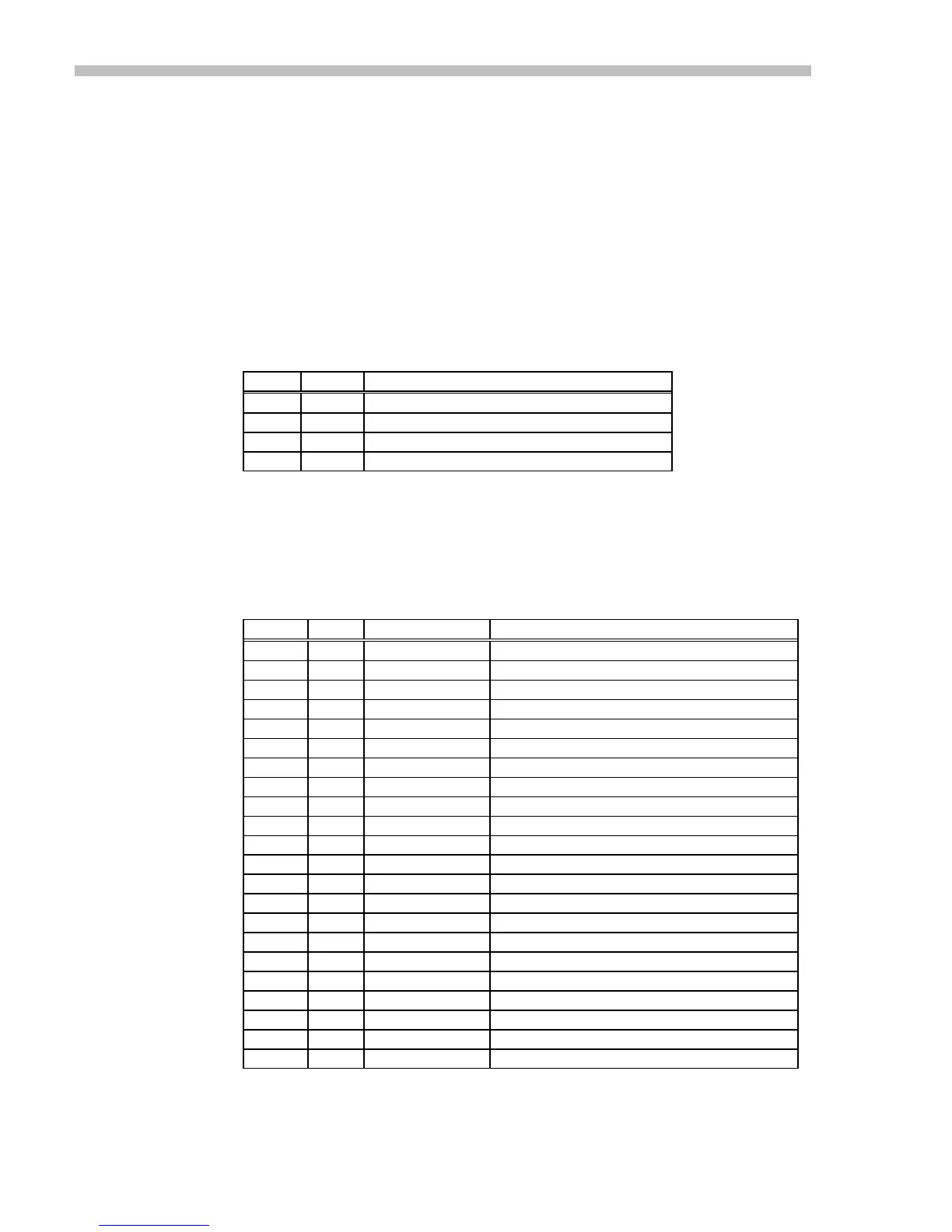
4 Pin power connector
Type Remarks
AA
P +HV, the high-voltage DC power input
BB
O Out- , or negative output
CC
O Out+, or positive output
DD
P Ground and +HV power return
Table 1
22 Pin signal connector
Note that pins are referred to by letter and number. The letter refers to the functional
schematic. The number is the actual connector-pin number on the cable header that
connects to the amplifier.
-Pin- Type Signal Remarks
1 (A)
I +Ref Differential (+) reference signal input
2 (B)
I -Ref " (-) " " "
3 (C)
P Signal Gnd Gnd for tachometer, signal gnd
4 (D)
O Ref amp out Output of differential input amplifier
5 (E)
I Aux input Auxiliary input
6 (F)
O
+11V
20K ohms in series with +11V
7 (G)
P Logic gnd Gnd for Enable inputs
8 (H)
O -11V 20K ohms in series with -11V
9 (I)
N.C. No connection to this pin
10 (J)
I /Reset LO or Gnd to reset fault condition
11 (K)
O Preamp out See schematic
12 (L)
Opt. ext. comp See schematic
13 (M)
I Tach input Tachometer input
14 (N)
Opt. ext. comp See schematic
15 (O)
I /Enable LO or Gnd to enable amplifier
16 (P)
I /Pos Enable LO or Gnd to enable positive output
17 (Q)
I /Neg Enable LO or Gnd to enable negative output
18 (R)
O +14V 1K ohms in series with +14V
19 (S)
O Normal HI (+5V) when amplifier operating Normally
20 (T)
O +5V 2.49K in series with internal +5V
21 (U)
N.C.
22 (V)
O Current monitor Outputs +/-6V at amplifier peak current
Table 2
 Loading...