1 8665 Smart Router Overview
Currently, the control f unction ality can be run on ly o n the line units in slots 2 and 13, respectively
the leftmost and rightmost line units i n the network element. When both u nit s in slots 2 a nd 13 are
installed, the n etwork elem ent is fully redundant.
Note that the timing and alarm interfaces should be only used from slots 2 and 13.
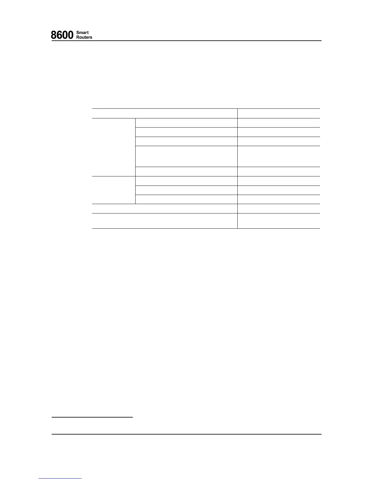
Control Plane Functionality Inside an LU1 Via CU
Feature
Control plane functionality
CPU cores
8 (Dual threaded 16)
Operating frequency
1666 MHz
Memory speed 1800 MH z (DDR3)
Cache memory 32K L1 I+D cache per core,
4M L2 cache in two clusters,
1M L3 cache shared
CPU
Routing memory (RIB) Approximately 3200 MB
Management Ethernet port One of the normal traffic interfaces
Serial console port Supported
Interfaces
Pulse per second (PPS) interface Supported
SD card Supported
Timing Integrated timing control functions
in baseboard
8665 Smart Router Switch Unit (SU1)
8665 Smart R o uter switch unit SU1 is used for packet switching inside the network element. SU1 has
two separate switches. The main data plane switch, which has a capacity of 900 Gbps, a nd a separate
control plane switch with a c
apacity of 90 Gbps. Althoug h almost full data plane capacity can be
reached with one SU1, it is strongly recom m ended to use two SU1s in a redundant configuration, as
the traffic load will be shared between the two SU1 s to enhance throughput and laten cy
1
.
SU1 contains the followi
ng functional featu res:
• High speed data links w ith all line uni ts
• Local power supply
• CPU for local mana
gement
• Packet based Switch Fabric
• Node control packet switch
1.1.3 Cooling
8665 Smart R o uter has three hot swappable fan modules.
1
When there is only one SU1, packet header terminations and a dditions, packet s ize and other factors affect the throughput.
76.8670-40128B 8600 Smart Rou ters
© 2015 Coriant. 8665 Smart Router FP7.0 Reference Manual
23