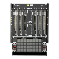
1 8665 Smart Router Overview
While dim ension ing different th ings at the cen tral offices and other telecommunications sites,
the information about the power consumption of th e NE or the current drawn by the NE may be
needed. C o oling of the telecommunications site might be a good example for the form er case and
dimensioning of the cables and circuit breakers for the latter. The maximum current for the NE can
be calculated by dividing the suitable evaluated maximum power consumption of the NE for the
purpose by the low e st specified battery voltage for t he NE.
1.4 Synchronization
8665 Sm art Router has a common timing generator. It is e specially needed when sy nchronous
Ethernet interfaces are in use. The generator is located on every LU1, and the timing reference
signals are distributed to every unit in the NE via the backplane.
The Timing Module provides a Syn chrono us Equipment Clock (SEC) or Stratum 3 g enerator
complying with t he relevant requirements. Typ ically, the NE is synchronized with a clock derived
from any of the following inp ut signals:
• LU1 interfaces: 10GBASE-R and 1000BA SE-X
• Station Clock Input signal (E1/DS1)
• Station Clock Input clock (E1 G.703 20 48 kHz)
For details of the synchronization functionality please refer to 8600 Smart Routers
Synchronization Configuratio n Guide.
The selected reference signal must be originated from an equipment having, at least, the SEC quality
clock, that is, the reference signal quality must be as defined in [ETS 300 462-3] and [EN 300
462-5-1] or [GR-253-CORE]. This m eans, for instance, that a 2048 kHz signal which complies with
[G.703] jitter and wander requirements may not be used as a reference.
When 8665 Smart Router is equipped with one L U1, the NE h as one station clock interface ( S CI) ,
i.e. one input and one output port. With a redund ant configuration both ports are duplicated and 1+1
protection is provided. The protecting port has a common parameter set with the protected port.
Both L U1 drive their own statio n clock output (SCO) port separately.
1.5 8665 Smart Router Redundancy
1.5.1 Control Redundancy
8665 Smart Router can provid e protection v ia the control functionality (CU). When two equal LU1
are installed in slots 2 and 13, 1+1 protection is provided f or th e NE control functionality and
for synchronization , if present i n the line unit. At the same t ime, the power feed functionality
utilizes a prot ection whe re the input with a h igher volt age feeds the NE. A critical failure in the
active LU 1, where the CU is running, will trigger an automatic switchover to a redundant LU1.
On the other hand, a failure in the NE power distribution will not cause a switchover because the
DC inputs are shared continuo usly.
8665 Smart Ro
uter LU1 does not have a dedicated MFE (Management Fast Ethernet) port, instead
any available Ethernet port can be used as managem ent interface. If this port needs to be protected,
ELPshouldbeusedtoprotectit.
76.8670-40128B 8600 Smart Rou ters
© 2015 Coriant. 8665 Smart Router FP7.0 Reference Manual
27