2 Line Unit (LU1)
The timing block has the following main functional eleme nts:
• Temper a tur e compensated SEC/Stratum 3+ oscillator with PLL and holdover logic
• Station clock interface with PLL and framer
• Reference clock selection logic
• Clock monitoring logic
The Network Element Clock is distributed via t he backplane to each line unit where the interfaces
supporting synchronization v ia Synchronous Ethernet may use it as a Tx reference. In the opposite
direction, the recovered line clock can be transferred to the timing block and, depending on the
configuration, the Network Element Clock is able to use it as a reference. The m onitoring logic takes
care that the selected reference clock is valid. It also monitors the operation of both PLL and other
available reference clocks set on the fallback list (contains clock sources/priority o rder selected by
the user). If all the clock sources fa il, the Netwo rk Element Clock will enter into holdover mode and
maintain the frequency and phase drift within the specified limits.
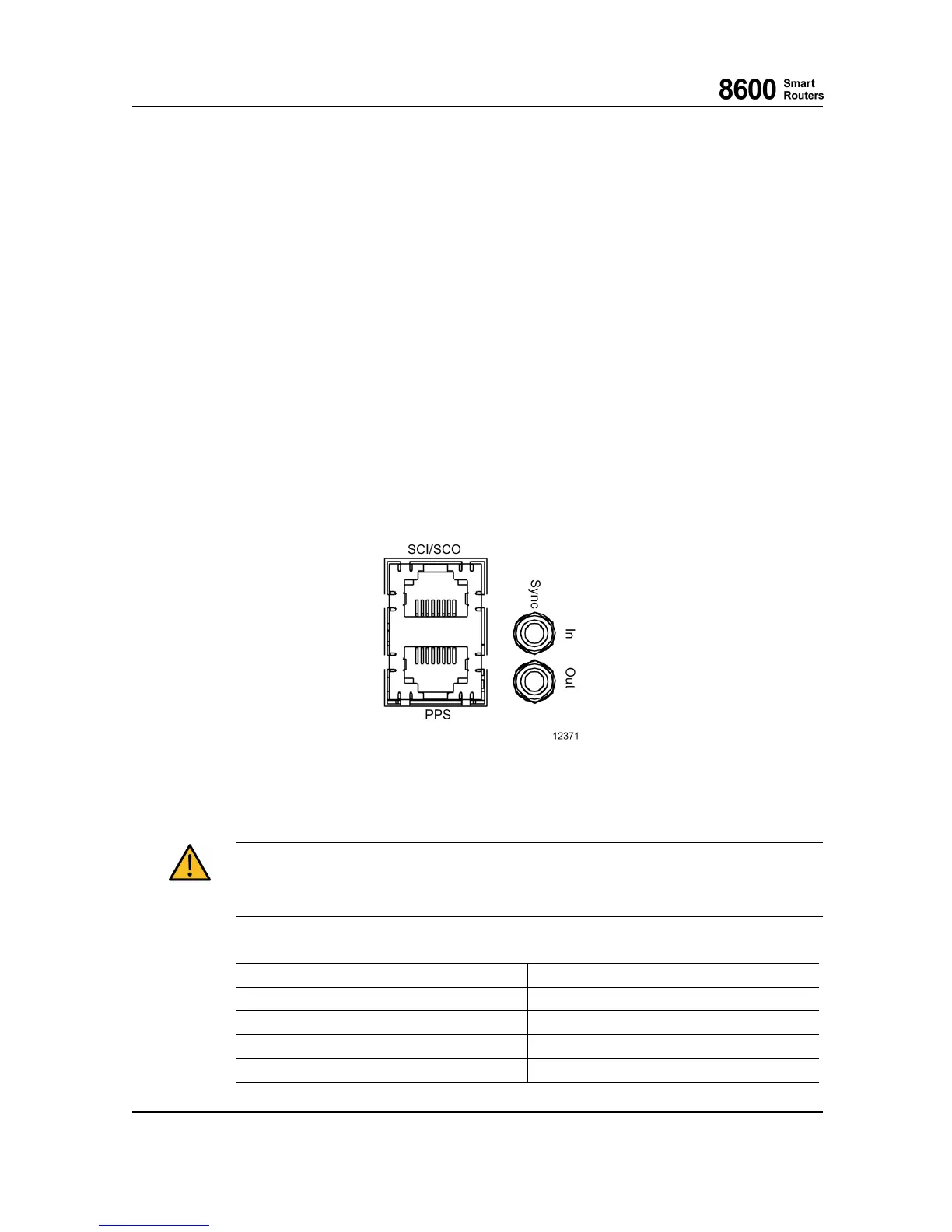
The statio n clock input/output interface is on the front plate of t he timing block. Depend ing on the
user needs, either coaxial or differential cabling can be used with a correspondin g connector, i.e.
SMB or R J-48c. The front panel has also the Time of Day and Pulse Per Second (PPS) interfaces in
an RJ-45 connector. The Time of Day and PPS interfaces use a point-to-point I TU-T V.11 interface.
Fig. 5 866 5 Smart Router Timing Front Panel Connector s
The port must be connected to the same type of port with proper cable, otherwise network
element functionality may be affected or physical dama ge may occur. Long cables should be
terminated properly to reduce interference.
Station Clock Interface Signals of RJ-48c, Female 8 Pins
Pin #
Description
1
Input A-wire (ring)
2
Input B-wire (tip)
3
Not connected
4
Output A-wire (ring)
8600 Smart Rout ers 76.8670-40128B
8665 Smart Router FP7.0 Reference Manual © 2015 Coriant.
32