2 Line Unit (LU1)
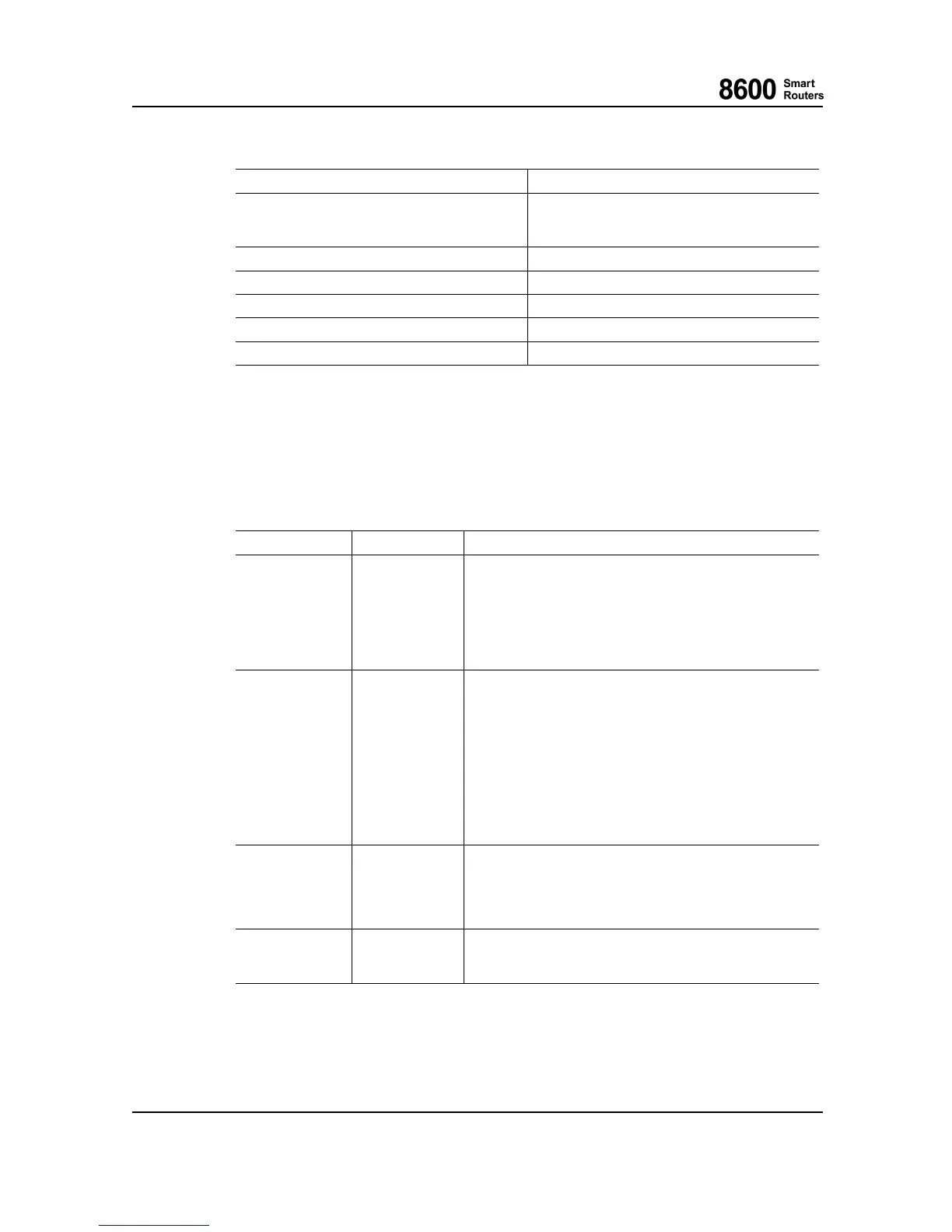
RJ-45 Female Alarm Connector Pin Map
Pin
Signal Name
8
6
7
General Out (NC)
General Out (NO)
General Out (Com)
1 Input1
2 Input2
3 Input3
4 Input4
5
GND
2.6 LU1 LEDs
2.6.1 LU1 Status LEDs
There are four LEDs to indicate the LU1 status and on e for the pow er OK status.
LED Name
Color States
Local Alarm
RED
ON when NE itself has a fault.
BLINKING during the following operations:
1) M anually set to forced blinking.
2) If also yellow LED is blinking, the card/NE ha
s reached
shutdown state after "esw-shutdown" command and can be
removed from N E or power can be switched off.
OFF otherwise.
Remote Alarm
YELLOW
ON when online and NE detects or suspects a fault in another
NE or remote site.
BLINKING during the following operations:
1) Boot-up sequence.
2) Inventory create.
3) Inventory (backup) restoration.
4) M anually set to forced blinking.
5) If also red LED is blinking, the card/NE has reached
shutdown state after "esw-shutdown" command and can be
removed from N E or power can be switched off.
OFF otherwise.
OnLine
GREEN
ON when NE is online (it is “up” meaning successful boot-up
sequence finished and startup permission granted). Note that
online NE may still contain errors.
BLINKING when CU is active.
OFF otherwise.
Power
GREEN
ON when NE power is ON and und
ervoltage not detected.
BLINKING Power supply failure.
OFF otherwise.
2.6.2 LU1 Ethernet LEDs
There are two LEDs to indicate the LU1 Ethernet port status.
8600 Smart Rout ers 76.8670-40128B
8665 Smart Router FP7.0 Reference Manual © 2015 Coriant.
38