3 Switch Unit (SU1)
RTC
The real time clock has backup for short power b r eaks. The tim e is kept for at least 20 hours (at
20º C/68º F).
A/D Converter
There is an analog to digital converter on the baseboard. It is used for measuring a nd monitoring
operating voltages and temperatures.
3.3.2 FPGA Subsystem
The FPGA subsystem implements the switch m atrix fu nctionality for the NE at 900 Gbps.
3.3.3 Control Ethernet Switch
The control Ethernet switch is used f or NE internal communication and it is fully separated from
the normal data plane.
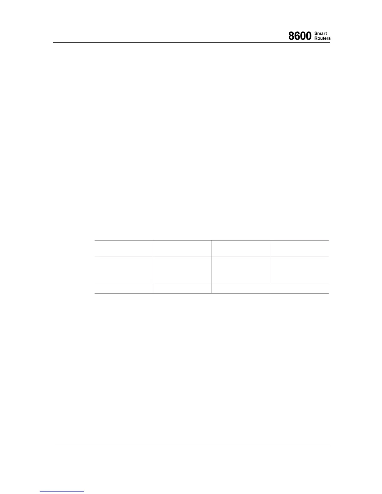
3.3.4 Backplane Data Links
Near End Unit Remote End Unit Remote Device
Effective
Bandwidth
SU1 LU1
Switch Fabric FPGA 130 Gbp/s with one
operational SU1
200 Gbp/s with two
operational SU1s
SU1 LU1
Control ethernet switch 10 Gbps
3.3.5 Power Supply
SU1 contains an integrated power supply (DC/DC converters) on board. It generates all t he voltages
which are needed within diff
erent blocks. The input voltag e is fed by either of the PIM s (redundancy
with two PIMs). The generated output voltages are galvanically isolated from the bat tery voltage.
SU1 has a polarity protection for wrong polarity.
3.3.6 Test Features
During boot-up, SU1 performs self tests to verify that the system operational status is nominal.
During normal oper
ation, the CPU m onitors the following:
• SU1 operatin g voltages.
• Temperature inside SU1.
8600 Smart Rout ers 76.8670-40128B
8665 Smart Router FP7.0 Reference Manual © 2015 Coriant.
42