4 Po wer In put Module
4.3 Front Panel and Connectors
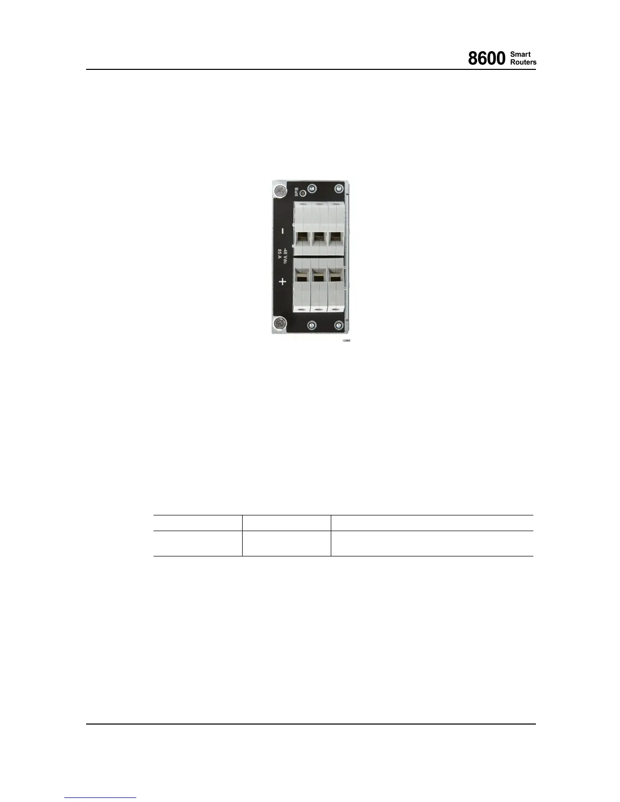
The following figure shows the PIM front panel.
Fig. 13 8665 Smart Router Power Input Module
The input connecto r is located on the front side of the PIM. The -4 8 V d c output voltage and sign al
connector is located on the back side of the PIM.
4.4 Input Fault Detection and LEDS
On the PIM there is a voltage m onitor for input voltage detection. If the inpu t voltage after the
fuse is missing or too low, an alarm is forwarded to the CU on the LU1, and a LED indicates the
input voltage status.
LED Name
Color States
Battery Voltage
GREEN
ON when Input voltage is valid.
OFF otherwise.
4.5 Cabling
The PIM can be used with normal copper power cables as screw terminals are used. The maximum
conductor cross section is 25 mm
2
(solid), 16 mm
2
(stranded) and 16 m m
2
(with ferrule). The
router can be wired with either single power cable pair or two pairs o f cables if thinner cable is
preferred in the installation.
Also a grounding cable with the same or thicker cross-sectional area than the power cable must
be used w ith the 8 665 Smart Router subrack with PIMs installed; that is, at least 16 mm
2
(approximately 5 AWG) or 25 m m
2
(approximately 3 AWG). For more details on power and
grounding cabling, please refer to 8600 Sma r t R ou ters Hardware Installation Guide.
8600 Smart Rout ers 76.8670-40128B
8665 Smart Router FP7.0 Reference Manual © 2015 Coriant.
46