INSTALLATION, OPERATION AND MAINTENANCE MANUAL – COSA 9610™
25 | Page
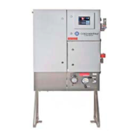
2.3.2. COSA 9610™ in general purpose execution
The COSA 9610™ is mounted to a freestanding stainless-steel frame. Fixing lugs are
located on each corner of the cabinet. Fixings used must be suitable for the weight of
the COSA 9610™ (±331 lbs/150kg).
The COSA 9610™ must be mounted on such a level above the floor or underneath
located obstacles that the oven drain can be connected to a drain header or a
condense bottle.
The COSA 9610™ is supplied on a 304SS freestanding frame. This frame is to be placed
on a flat surface (i.e. concrete slab). Two holes in the base of the frame enable the
COSA 9610™ to be fixed to the floor.
2.4. MECHANICAL CONNECTIONS
2.4.1. General
•
Location and number of connections may vary depending on type and
execution of the analyzer. See the project specific drawings of your order.
•
Tubing connections on the COSA 9610™ are Swagelok double ferrule
compression type fittings for imperial sizes. Reducers to metric fittings or
NPT thread are available.
• Only seamless and annealed imperial size instrument tubing according to
ASTM A-249 at a maximum permissible hardness of Rockwell B-90 may
be used.
• Tubing must be cut off straight and de-burred thoroughly inside and outside of
tubing cutting edge.
• The outside surface of the tube ends entering the fittings must be clean
and free from scratches.
• Nuts and ferrules should not be removed to avoid mixing up of the nuts
and or ferrules.
• Tubing must be pushed into the fitting onto the seat.
• Hand-tighten the nut and mark the nut against the fitting.