INSTALLATION, OPERATION AND MAINTENANCE MANUAL – COSA 9610™
28 | Page
2.5.2. Analyzer electronics (NEC US application).
The power must be connected on the interference filter inside the electronics cabinet.
The cable must lead into the analyzer through a suitable approved conduit and conduit
adapters.
The COSA 9610™ has multiple input and output signals, which can be split in two
groups, analog and digital signals. For both groups, a suitably certified cable gland for
use with multi core cables are foreseen for ATEX use and suitable conduit and conduit
adapters for North American installation.
If more entries are required, only suitably certified cable glands or conduit adapters are
allowed to be used and it must be made sure that they are in good electrical contact
with the white personated sink layer on the electronics enclosure surface (paint locally
to be removed with a detergent).
For termination details see project specific drawings.
3. IN OPERATION
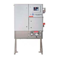
3.1. START-UP SAMPLE CONDITIONING SYSTEM
The sample conditioning system is located in the left-hand compartment. This chapter
describes how the components of the sample conditioning system should be set up, in
correct order, so a perfect start-up of the total analyzer system can be achieved. The
instructions hereunder should be performed step by step.
3.1.1. Inspection, visual and external connections
Perform a visual inspection of the system and close all shut-off valves in the system.
Check the connecting fittings of the supply tubes to be correctly fitted and are not
leaking. This can be checked quite simple by unscrewing the nut from the fitting and
then check if "Front and Back ferrule" of the fitting is able to rotate but cannot be
moved in an axial direction. If this is not the case, this tube must be renewed. Then
turn the nut by hand and afterwards tighten it a 1/4 turn with a suitable spanner. The
supply and drainage tube can now be connected.
Because the supply line is under pressure and has been closed off on the COSA 9610™