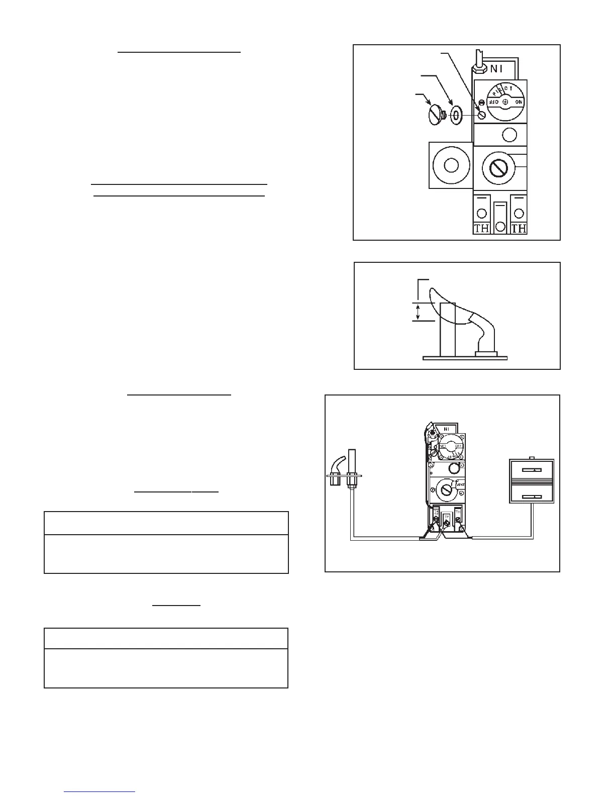
PILOT ADJUSTMENT
Locate pilot adjustment cap on valve and remove. See Figure 8.
Pilot flame should surround the top 3/8 to ½ inch of powerpile or
thermocouple, see Figure 9. To increase pilot flame, turn pilot
adjustment screw, see Figure 8, counterclockwise. To decrease pilot
flame, turn screw clockwise. After a proper pilot flame is established
replace pilot adjustment cap, be sure gasket located on bottom of
cap head is in place. The gas supply to the pilot is unregulated.
When line pressure exceeds 7” w.c. Natural Gas, 11” w.c. L.P. Gas,
pilot adjustment must be made.
TO REMOVE MAIN BURNER FOR
INSPECTION AND CLEANING
1. Remove outer casing.
2. Disconnect gas supply to valve.
3. Remove 11 screws holding burner door to heat exchanger and
lift out complete burner, valve assembly.
4. After inspecting burner, place back into heat exchanger. Be
sure door gasket is not damaged and will effect a proper seal or
pilot outage will occur.
5. Tighten screws holding burner door to heat exchanger.
6. Connect gas supply back to valve.
7. Install front panel and follow lighting instructions.
NOTE: The furnace and all components must be inspected at least
annually by a qualified service technician. This should include
the burner, heat exchanger, and vent system. Be sure that the
flow of combustion and ventilation air are not obstructed.
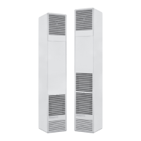
BURNER ORIFICE
This appliance is orificed at the factory for elevations up to 2,000 ft.
If installed above 2,000 ft., the BTU input must be reduced 4% per
1,000 ft. See the following orifice chart for the proper orifice for a
specific elevation. Orifice change must be completed by a qualified
installer or service technician.
Pilot Adj. Screw
Gasket
Pilot Adj. Cap
FIGURE 8
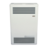
WIRING DIAGRAM
Pilot Generator
Leads
Thermostat
Wire
WIRING DIAGRAM
CAUTION: Label all wires prior to disconnec-
tion when servicing controls. Wiring errors can
cause improper and dangerous operation. Verify
proper operation after servicing.
Page 10
FIGURE 9
Pilot flame should envelop
3/8” - 1/2” of powerpile
or thermocouple
NATURAL GAS
SPECIFIC ELEVATIONS
MODEL 0 TO 2,000’ 4,000’ 6,000’ 8,000’
NUMBER 2,000’ 4,000’ 6,000’ 8,000’ 10,00’
CDV155B 48 49 50 51 52
CDV255B 2.45mm 41 42 43 44
CDV335B 2.75mm 37 38 40 42
ORDER KIT #49800 44-1 HIGH ALTITUDE KIT
L.P. GAS
SPECIFIC ELEVATIONS
MODEL 0 TO 2,000’ 4,000’ 6,000’ 8,000’
NUMBER 2,000’ 4,000’ 6,000’ 8,000’ 10,00’
CDV156B 1.2mm 56 57 59 60
CDV256B 1.55mm 54 54 55 55
CDV336B 1.65mm 51 52 52 53
ORDER KIT #49800 44-1 HIGH ALTITUDE KIT