INTRODUCTION
THIS IS A GAS-FIRED, DIRECT VENT WALL FURNACE THAT WILL OPERATE SAFELY AND
PROVIDE AN EFFICIENT SOURCE OF HEAT WHEN INSTALLED, OPERATED AND
MAINTAINED AS RECOMMENDED IN THESE INSTALLATION AND OPERATING
INSTRUCTIONS. READ THESE INSTRUCTIONS THOROUGHLY BEFORE INSTALLING,
SERVICING, OR USING THE APPLIANCE. IF YOU DO NOT UNDERSTAND ANY PART OF
THESE INSTRUCTIONS CONSULT LOCAL AUTHORITIES, OTHER QUALIFIED INSTALLERS,
SERVICE TECHNICIAN, THE GAS SUPPLIER OR THE MANUFACTURER.
Page 2
SAFETY RULES
1. Improper installation, adjustment, alteration, service, or maintenance can cause property damage, bodily injury, or death.
2. Use in other than a residential application may result in unsatisfactory performance and may void the warranty.
3. This appliance must be installed in accordance with local codes, if any; if not, follow the National Fuel Gas Code ANSI
Z223.1/NFPA 54 or the National Gas and Propane Installation Code CSA-B149.1.
4. Do not install this wall furnace in a recreational vehicle or trailer.
5. Do not operate wall furnace unless it is connected to the supplied vent system with vent cap in place.
6. Check the rating label attached to the wall furnace to be sure it is equipped for the type gas you intend to use.
7. Never use a match, candle, flame or other source of ignition to check for gas leaks. Use only soapy water or liquid detergent.
8. Have your wall furnace and vent system inspected at least annually by a qualified service technician.
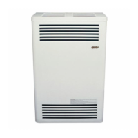
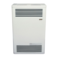
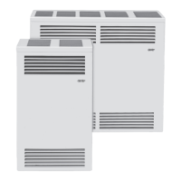
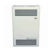
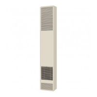
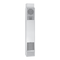
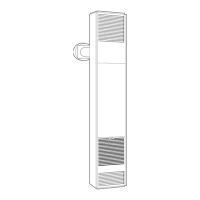
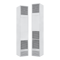
SPECIFICATIONS AND DIMENSIONS
Your Direct Vent Wall Furnace is shipped complete in one carton. This carton contains the furnace, vent
cap, vent tube, air inlet tube, template with rough-in dimensions, installation and operating instructions, and
the thermostat with thermostat wire (if applicable). NOTE: There will be two cartons if optional vent kit
or blower is purchased.
MODEL INPUT GAS TYPE MAX. WALL MIN. WALL
NO. BTU/HR. WIDTH DEPTH HEIGHT CONN. GAS THICKNESS THICKNESS
CDV155B 15,000 18” 9-3/4” 29-3/4” ½” NAT. 24” 5”
CDV156B 15,000 18” 9-3/4” 29-3/4” ½” L.P. 24” 5”
CDV255B 25,000 34-1/2” 9-3/4” 31-3/4” ½” NAT. 24” 5”
CDV256B 25,000 34-1/2” 9-3/4” 31-3/4” ½” L.P. 24” 5”
CDV335B 33,000 34-1/2” 9-3/4” 31-3/4” ½” NAT. 15” 5”
CDV336B 33,000 34-1/2” 9-3/4” 31-3/4” ½” L.P. 15” 5”
CONTENTS
Introduction……………………………. 2
Specifications and Dimensions…………. 2
Safety Rules……………………………. 2/3
Clearances……………………………… 3/4
Location……………………………….. 5
Installation………………………………. 5 - 8
Vent Kits.................................................. 5 - 7
Gas Connection....................................... 8
BBSK Instructions................................... 12/13
Lighting Instructions…………………… 9
Pilot Adjustment……………………….. 10
Burner Orifice…………………………… 10
Wiring Diagram………………………… 10
Removing Main Burner………………… 10
Proper Burner Flame…………………… 11
Thermostat Installation………………… 11
Installing Optional Blower Kit………… 11
Maintenance Instructions......................... 19
Trouble Shooting………………………. 18
Parts Drawing………………………….. 14//16
Parts List……………………………….. 15 /17
Warranty……………………………….. 21
The State of Massachusetts requires that installation and service of a gas appliance be
performed by a plumber or gas fitter licensed in the Commonwealth of Massachusetts.