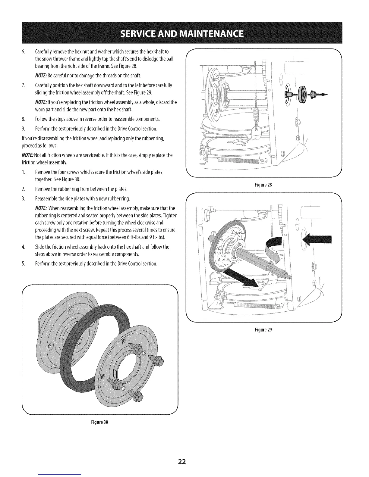
6. Carefullyremovethehexnutandwasherwhichsecuresthehexshaftto
thesnowthrowerframeandtightlytaptheshaft'sendtodislodgetheban
bearingfromtherightsideoftheframe.SeeFigure28.
NOTE:Becarefulnotto damagethethreadsontheshaft.
7. Carefullypositionthehexshaftdownwardandtothe[eftbeforecarefuNy
slidingthefrictionwheelassemblyoff theshaft.SeeFigure29.
NOTE:Ifyou'rereplacingthefrictionwheelassemblyasawhole,discardthe
wornpartandslidethe newpart ontothehexshaft.
8. Followthestepsaboveinreverseorderto reassemblecomponents.
9. Performthetestpreviouslydescribedinthe DriveControlsection.
If you'redisassemblingthefrictionwheelandreplacingonlytherubberring,
proceedasfollows:
NOTE:Notallfrictionwheelsareserviceable.Ifthisisthecase,simplyreplacethe
frictionwheelassembly.
1. Removethefourscrewswhichsecurethefriction wheel'ssideplates
together.SeeFigure30.
2. Removetherubberringfrom betweenthe plates.
3. Reassemblethesideplateswith a newrubberring.
NOTE:Whenreassemblingthefrictionwheelassembly,makesurethatthe
rubberring iscenteredandseatedproperlybetweenthesideplates.Tighten
eachscrewonlyonerotationbeforeturningthewheelclockwiseand
proceedingwith thenextscrew.Repeatthisprocessseveraltimestoensure
theplatesaresecuredwith equalforce(between6 ft-lbsand9 ft-lbs).
4. Slidethefrictionwheelassemblybackontothehexshaftandfollowthe
stepsaboveinreverseorderto reassemblecomponents.
5. Performthetestpreviouslydescribedinthe DriveControlsection.
f
f
Figure28
J
Figure29
J
Figure30
,J
22