Hardware Information D-9
Modem Connector Pin Assignments
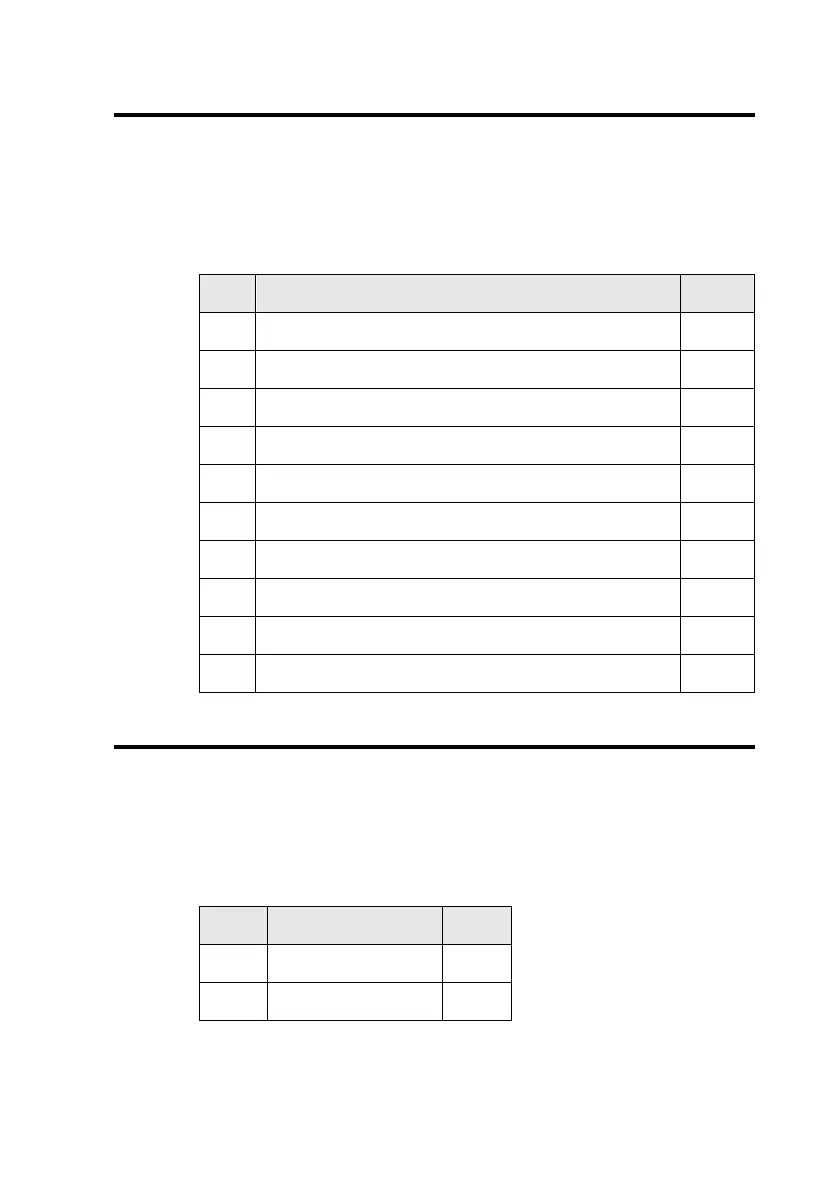
The Modem connector has the following pin assignments shown in
Table D-10.
PC Speaker Connector Pin Assignments
The PC Speaker connector has the following pin assignments as
shown in Table D-11.
Table D-10: Modem connector pin assignments.
Pin Description I/O
1 Analog Ground —
2 Pin is cut to provide keyed connection. N/A
3 Mono line level input from modem to Line In jack. In
4 Analog Ground —
5 Left channel line level audio output to modem. Out
6 Analog Ground —
7 Right channel line level audio output to modem. Out
8 Mono line level input from modem to PC Speaker. In
9 Analog Ground —
10 Microphone input from modem. In
Table D-11: PC Speaker connector pin assignments.
Pin Signal I/O
1+5V In
2PC Speaker Out In
This manual downloaded from http://www.manualowl.com